Back to Smartcitizen.me

Origin of the Noise dB(A) code?

The SckUrban.cpp files include a lot of code to figure out the dB(A) levels out of the ICS samples. Either the hardware or the code are wrong because the measurements are terribly too high.

But in order to make sense of the current code, what is the idea of it? The code is full of mathematical operations and numbers without any indication of source. So it’s hard to figure out what is wrong.

Can someone point at where all that code/numbers come from?
@victor (git annotate) ?

hi,

Could you maybe shed some light about the problem with the high values?

The code reads samples of the I2S and makes a FFT, for later on applying a dBA/C spectrum scale and equalise the microphone response (from datasheet and also tested in an anechoic chamber). The spectrum bins can be also read in console and the weighting function selected (A, C or Z – none). The code comes from an initial implementation based on ArduinoSound, later on stripped by @victor to fit in the samd21 memory, since all the arm math dsp core is too large. All the corrections are based on this matlab/octave code, although the cpp code includes further equalisation for hardware’s non-linear behaviour.

it is possible that there is something wrong in the code, but we tried to be quite careful with all the math behind it and verifying with the tests in the chamber. Nevertheless, if you find something or want to share test results here we would be more than happy to check them out.

Regards!

I am in a silent room and it reports ~48dBA. I have never seen it below 46dBA.
46dBA is like being at 1 meter of an home air conditioning external unit.

This kit https://smartcitizen.me/kits/9606 reports a minimum of 60dBA (that’d be a normal conversation next to the ICS) and recurrent rises up to 100dBA (that’s a jackhammer at 1m). It makes no sense, I think.

I have a Trotec BS06 sonometer and it reports 31dBA in my room. Both SCK and Trotec sit close together.

(per cert, I run master branch code, fwiw)

Same here no value under 47dB.
But in general the value seems “proportional” to the ambient noise.

Proportional is a very strong term for these numbers. I guess you mean that the value seems related to ambient noise.

Yes exactly that’s why I used “”
Also same conditions give coherent measurements over time.

1 Like

Maybe @oscgonfer can give some information about the calibration process all went through? What is the explanation about the device returning dB values apparently so far off over expected values?

Ok, I might accept that it cannot measure below 45dBA. What is the measuring range then? What would be a kit self-check to do at home? Any idea with any known common source of noise?

Hi all!

First of all, many thanks for these comments. We went back to reviewing the code and we found one issue with the data processing. As with past issues, there is a fix already available in the firmware and it will be included in the next main release, but if you want to test it, use the instructions here to flash it and use the *.uf2 file that you can find here.

Below comes an in depth explanation of the issue, so get ready!

First let’s talk about how we process the noise samples. The whole in depth explanation is detailed in this series of posts (I, II, III), but we will make a summary here.

  1. Noise is sampled by a MEMS microphone by Invensense (TDK) ICS43432, at 44.1kHz. We take 512 samples, as this gives us a reasonably good noise spectrum, from very low frequencies (<100Hz) up to 22.05kHz. This basically covers human hearing in general (except for super humans and that kind of thing).

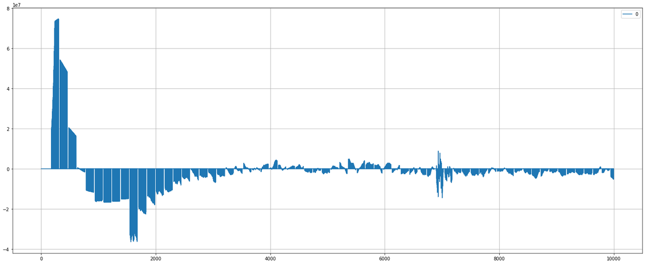
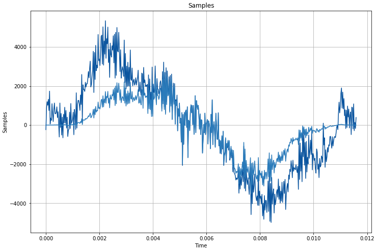
  2. The samples are then windowed using a hann window. This table is here and is applied to the samples here. Some raw and windowed samples are shown below for some tests I conducted at home. Mainly, the window is used to avoid introducing frequencies into the FFT (below) that are a byproduct of the discrete sampling process, or in other words, to smooth out the edges of our samples and avoid having peaks in the spectrum that do not exist.

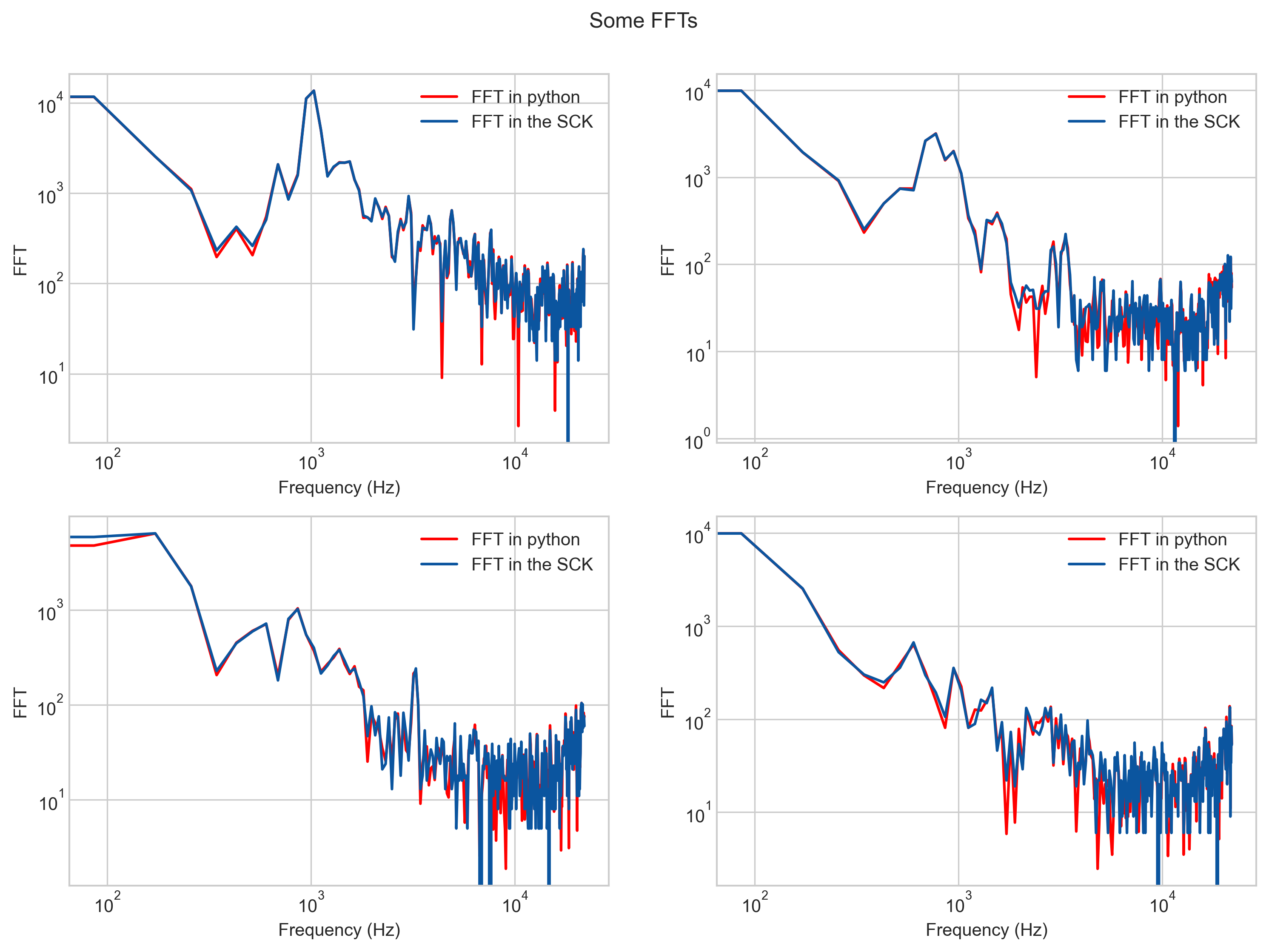
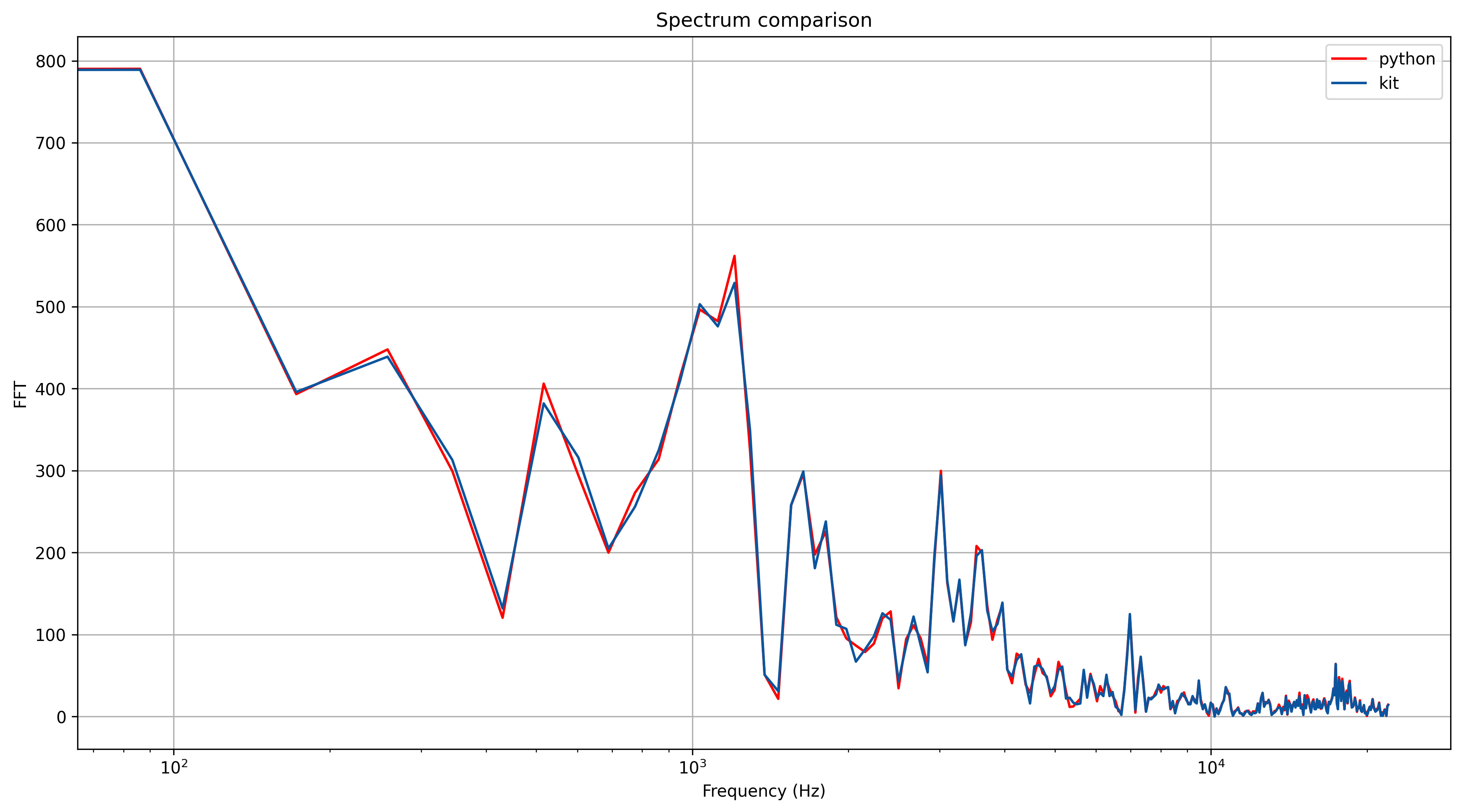
  1. With the windowed sample, we calculate the FFT algorithm. The implementation is a custom version based on Adafruit ZeroFFT because arm’s DSP core for making this operation is way too large for the SAMD21 chip and literally leaves no room for other things in the firmware. Therefore, we had to apply the algorithm ourselves by using these two lines and these two tables. The resulting FFT, calculated using this process, and compared with an FFT done in python is shown below. Luckily, the match almost perfectly (phew!)

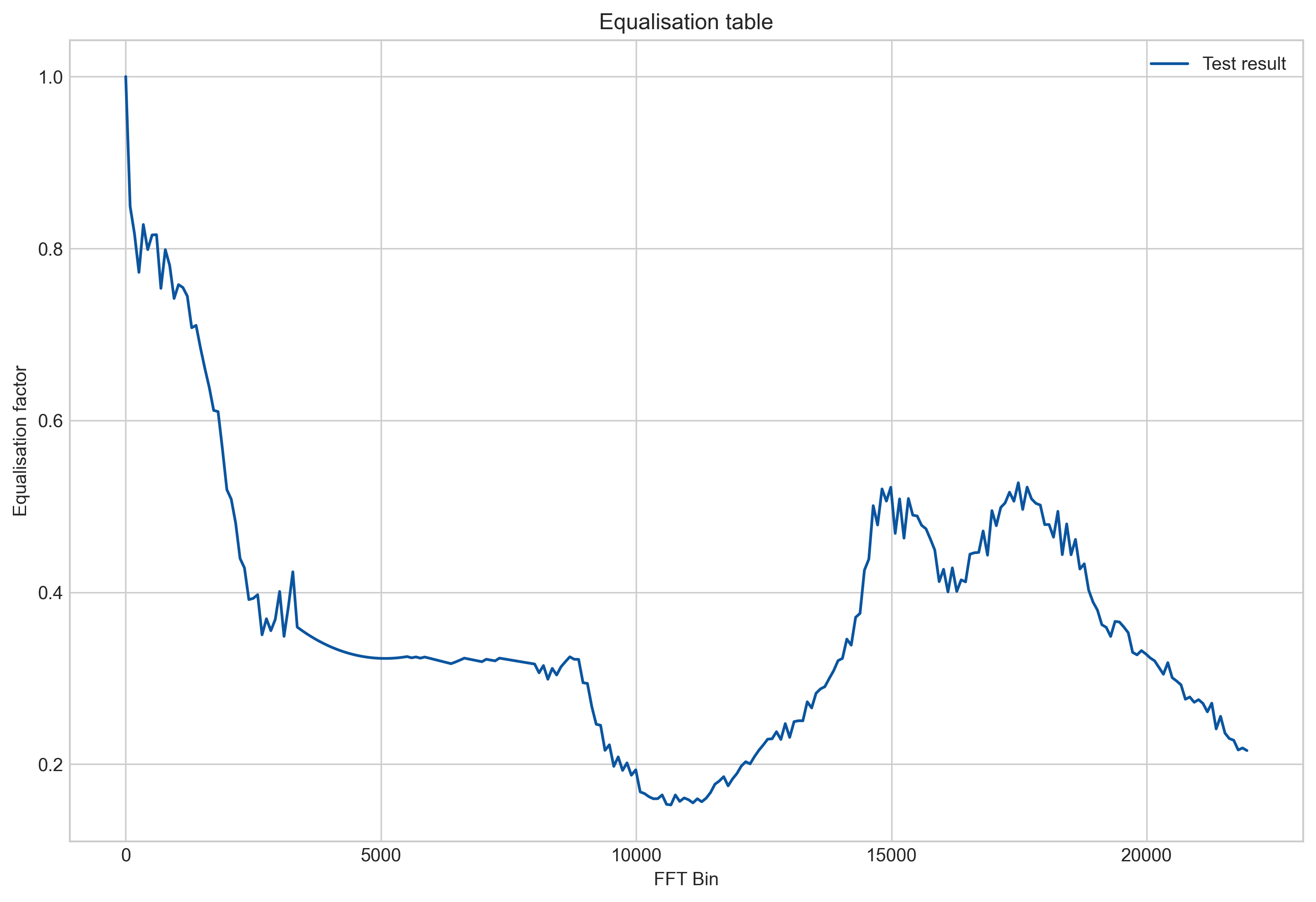
  1. Once we have the FFT spectrum, we perform two processes: equalisation and weighting. The equalisation process basically tries to correct the microphone response and make it linear. This is because the microphone responds by amplifying some frequencies more than other and we compensate this. To do so, we performed tests in an anechoic chamber and we extracted this equalisation table. This table matches roughly the response of the microphone, but also some other resonances from the urban board.

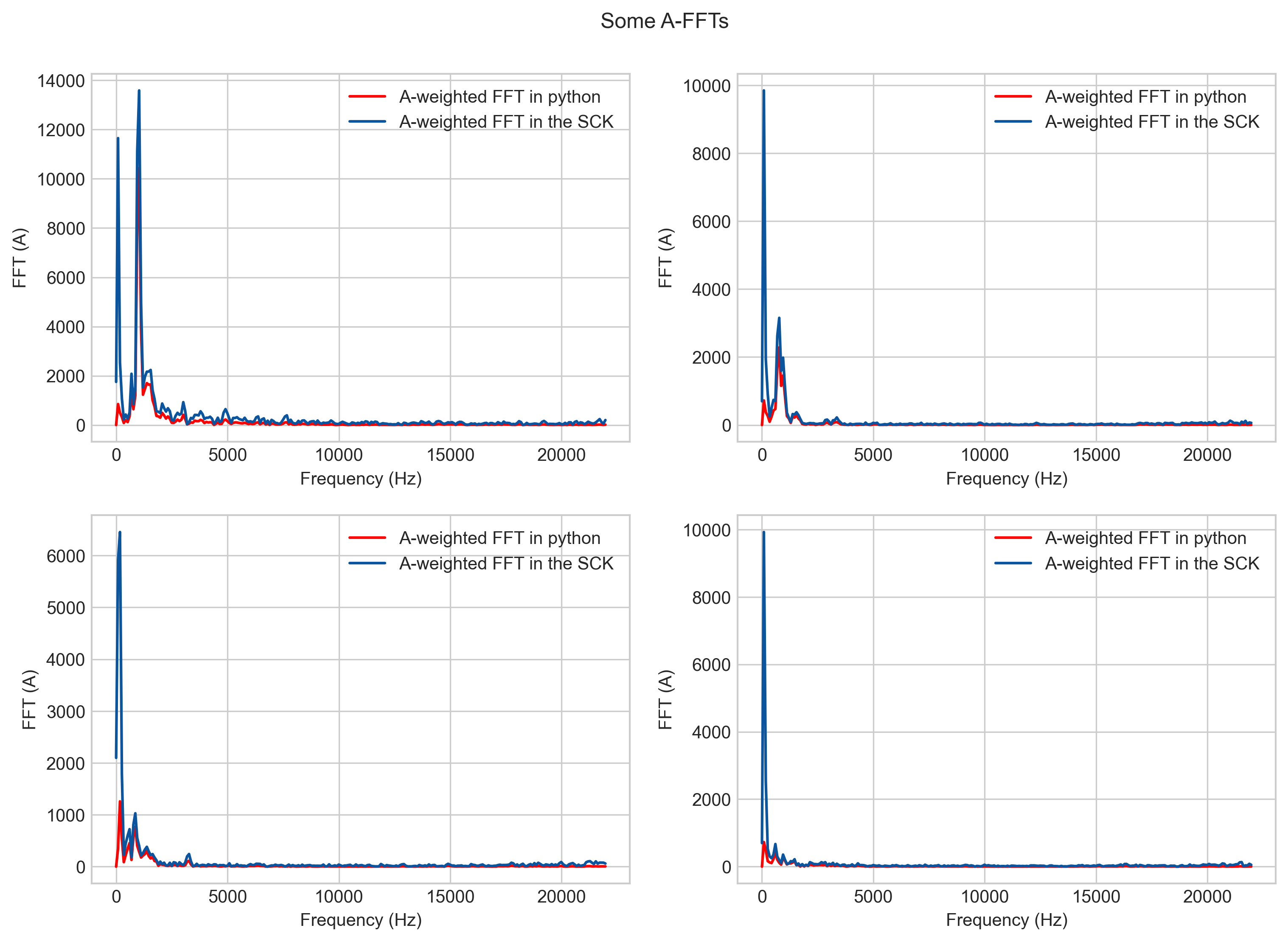
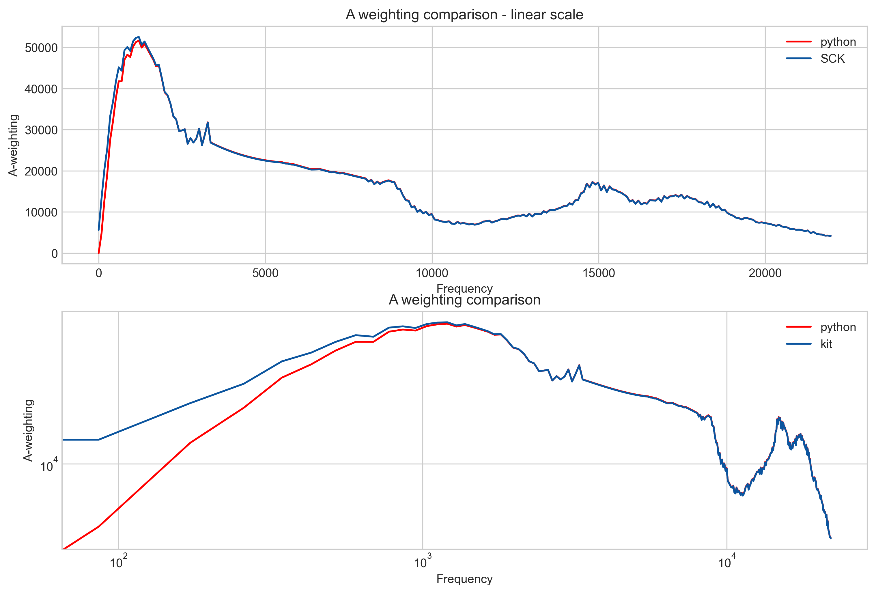
With this, we go on to the weighting, we apply A or C weighting to the samples:

Since these two processes can be combined, we put them in one single table for each weighting (A and C) and made them easier to handle by the chip by making them in the range of 0-65535.

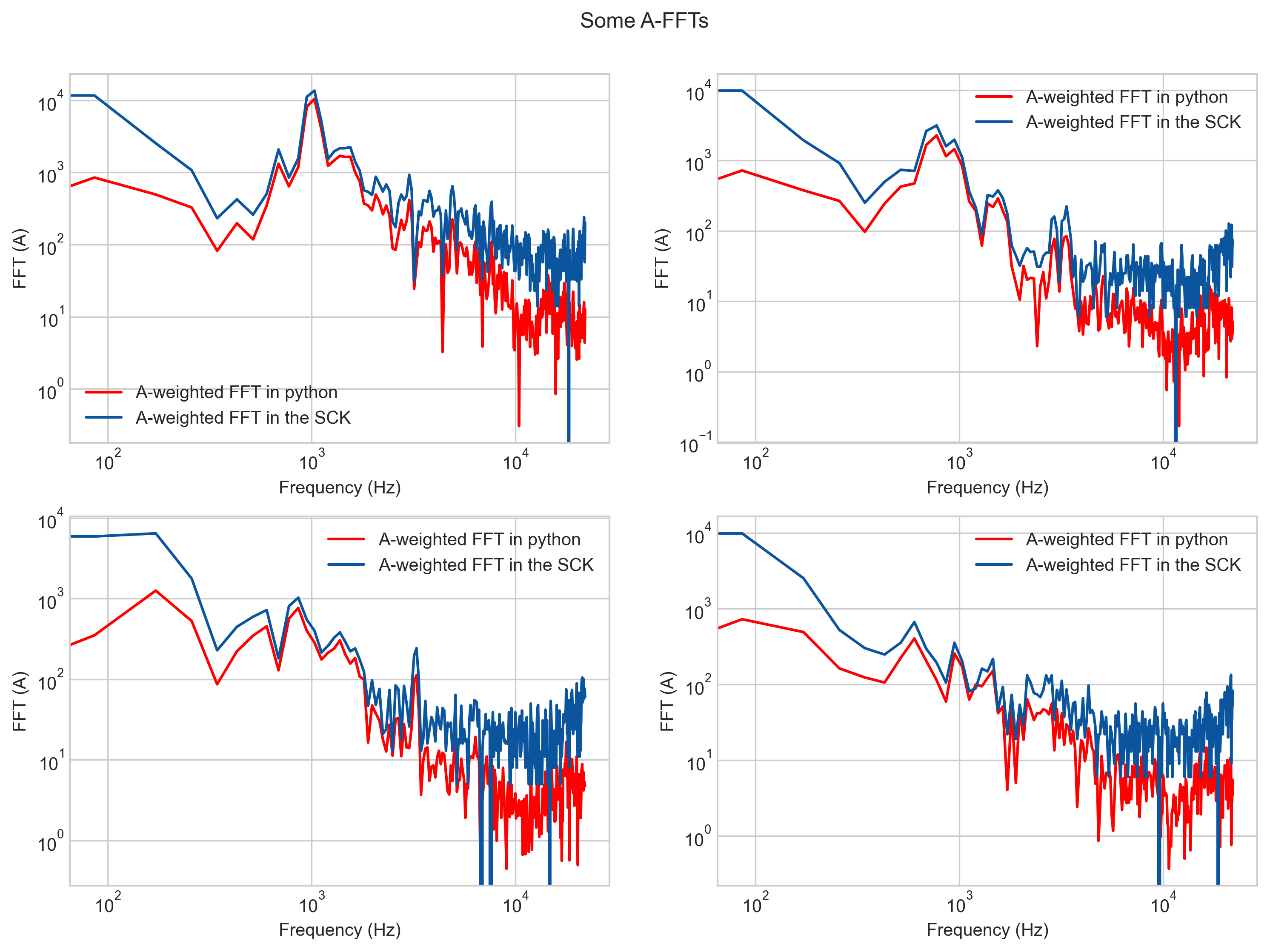
Looking closely enough, or in the log plot, you can see how: 1. some numerical errors start happening (not as bad), but more importantly, 2. the lowest frequency area doesn’t match at all! If we compare the RMS values now, we start to see a difference, specially for those spectrums that do not contain much information out of the f<500Hz.

And here is the mistake :boom: … The combination of the equalisation tables and the weighting was not right in the firmware, specially for A weighting:

This makes, that in quiet environments, there is an error by this “amplification” or better, lack of weighting. If we compare the RMS errors (in dB scale) in all four samples, we see how the lower we go in absolute spls, the worse this error becomes relative to the overall spectrum:

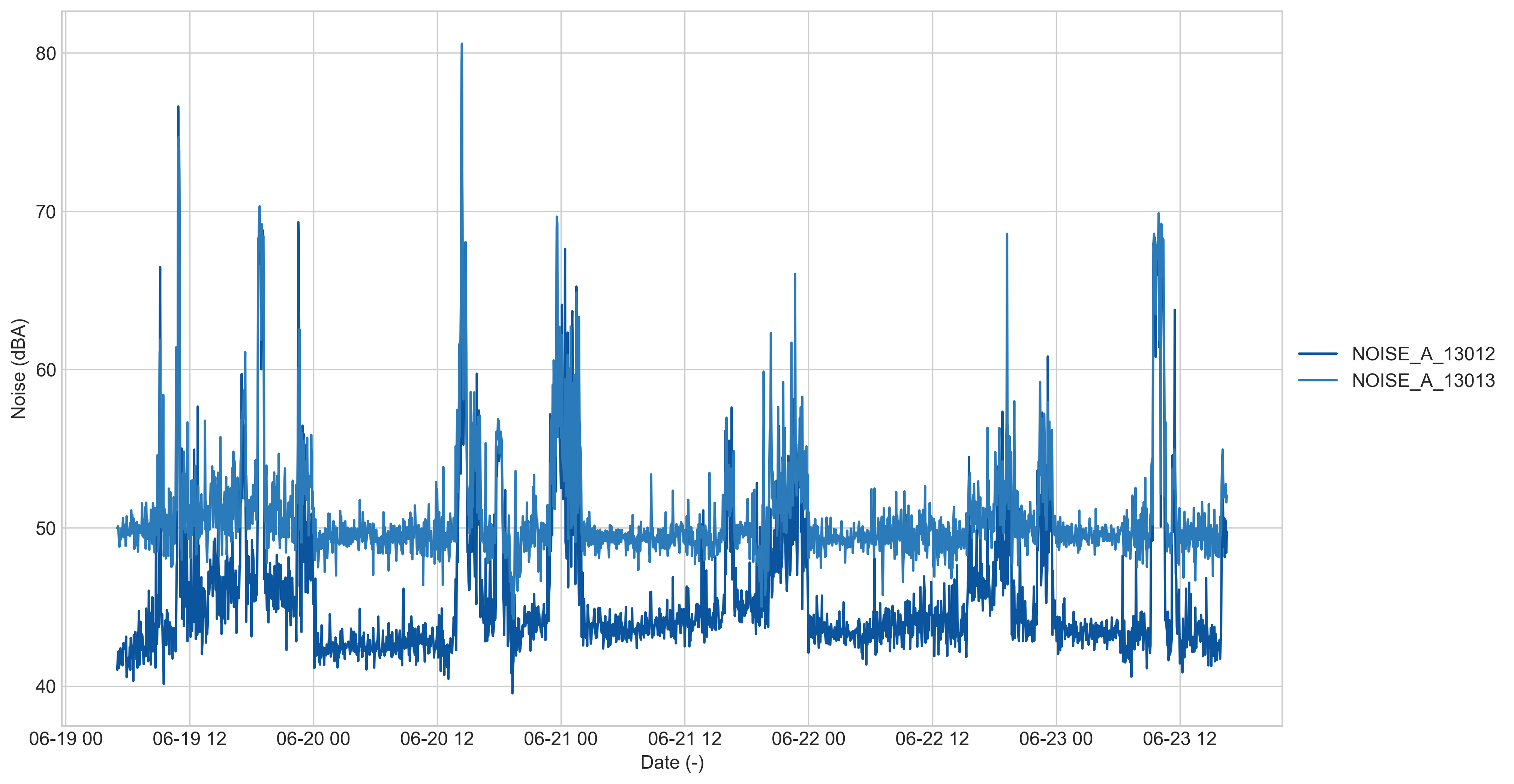
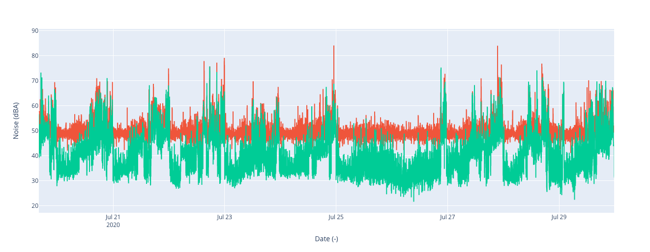
If now we measure with to SCKs, one with the fix and one without in an office environment (aka my room these days) and various noises around for testing, we can see how this bottom threshold is lowered:

Bug version: http://smartcitizen.me/kits/13013
New version: http://smartcitizen.me/kits/13012

Some questions might arise:

  1. Can measurements already recorded be fixed? No
  2. Can this be fixed? Yes. See the firmware comment above.
  3. Does this affect all the measurements? No, only those with very low frequencies and below 50-52dB approx.
  4. Is this it? In principle yes, but I invite you to test it and give us feedback, also to check the source code in the firmware and the python analysis below to see if we made any mistake in the process.

Note: all this processing is also available in this python notebook in case you want to review the calculations yourselves.

Thank you very much for your understanding and again, for commenting here and making us come back to the numbers and check the values.

2 Likes

Merci Òscar.

Looking at your approximation of FFT, it seems that it fails always above the python FFT. Isn’t the approximation increasing the energy of the signal? Is it preserving the energy the same as the FFT?

As for the sensor, what is the relationship between sample amplitude and sound preassure?

I don’t know anything about the chamber you mention, but I’d say that over 40dBA is a lot for a quiet room, if you are silent. About the calibration, was it done with the FFT approximation or the regular FFT?

Have you compared the measurements with another device that measures sound? Maybe the board makes some noise (as someone pointed out)?

Hi @viric,

The above FFT represents the “old” table. The new calculations, captured in a quiet environment match almost perfectly:

You can find the explanation here and in this note.

The anechoic chamber is a test cell that ideally suppresses all echoes. We went to one some years ago to perform the tests in an university in Barcelona. You can see the results here. This fact is important though: the corrections were performed with a prototype version of the device (arduino zero with the microphone) and there might be inaccuracies in the correction. We haven’t got the resources to go perform more tests in a chamber, so the equalization might differ, and resonances might not be fully corrected. You are absolutely right about the values in low dB (should be probable more towards 30-32dB in a very quite room) but with these corrections I have only been able to reach 37-38dBA. Note also that the noise floor in the chamber (really quiet environment) is approximately 30dBA.

Yes, but I don’t think the board itself is the source of the noise. The test setup I have at home has everything disabled, no PM sensor, no nothing, and still the quietest it goes is that. If we manage to visit an anechoic chamber again we might be able to correct this, but as of this moment, in my poor test environment, I would consider 38dBA the noise floor of the device.

1 Like

I find it hard to accept that the device measures at minimum 38dB; I’d say at minimum it should receive all samples zero, but I don’t know what dBAs that would mean. I haven’t thought this much :slight_smile:

About the FFT approximation, did you check if it keeps the energy of the signal compared to the regular FFT?

I also remember that the length of the sound signal was very short. Maybe you record 0,01 seconds of every 10 seconds. That could make a pneumatic hammer often invisible to the noise sensor. Do I remember right?

You didn’t answer, btw, the part of whether you compared your measurements with those of a regular sonometer. Sonometers usually include a foam against wind influence, for example. I don’t know much about sonometers but they seem somewhat designed beyond a MEMS microphone on a surface.

Just found a lead that has nothing to do with the FFT. We’re looking into it and we’ll post here once we have a clear fix. But yeah, we can go down to 30dBA and seems that even lower.

Keep you posted!

1 Like

What about that lead? Did this bring to any new code that makes more sense? Is there some complicated work to be done?

Hi,

Life happened and we couldn’t post more info here. However, we have been working and validating this and is now available for testing in the master branch in the firmware repository.

The problem was the following: the I2S microphone has a ramp-up period during the initialization that saturates the microphone up to full-scale, and then goes down to normal measurements. This period is not very clear in the datasheet, but it should be no longer than 100ms (datasheet here).

This is a raw recording of all I2S samples (the microphone reading) during the rampup period and after:

As it was in the previous versions of the firmware, we were measuring in the area of approx 2000 samples, which is still in a zone of negative saturation (and sadly not stated in the datasheet anywhere as far as we know). We have now increased the initialisation time of the microphone to avoid this area, and this solves the issue, as we are now in a non-saturated area. If you take a sample from this period, you can see how the samples are centered around 0, and it does not have the same upward trend as all the samples shown in the first post of this thread.

A comparison of the sound samples in our homes now shows no clipping in the lower end:

So… you were right, there was an issue that we hadn’t seen and took us quite a bit to find. Nevertheless, is now solved and available for you to apply as other times:

Make sure you have a look at the guides and that you can do so with both chips, SAM and ESP as shown here:

https://docs.smartcitizen.me/Guides/Update%20the%20firmware/

Let us know if there are any issues!

2 Likes

Good information thanks for sharing
vmware