This describes my project in outline:
Use Case: The goal is to comprehensively measure ground level ambient air pollution characteristics in a remote mobile scenario; in both urban and in pristine remote environments. We are concerned about air quality.
The Base system is a Smart Citizen Station comprising:
- Smart Citizen Kit V2.1 with Data Board (SAMD21G and ESP8266) and Urban Board: The base sensors are: Air Temp, Humidity, Absolute Air Pressure; Noise Level; Light Level; VOC Concentration. (Note: Dust Sensor is not fitted to urban board in this case). Wi-Fi Communications@ 2.4 GHz. is provided by ESP8266.
- Smart Citizen Station standard extensions to SCK include a PM Board with SAMD21G processor; and the sensors are External temperature (Dallas), and 2 x Dust Sensors. SCS also includes 3 x 16 bit Analog Digital Convertors to which are attached 5 x Electrochemical Gas Sensors. In this case we use sensors provided by Spec Sensors (USA) in place of Alphasense. This is due mainly to cost considerations. The sensors are CO, NO2, SO2, O3 and H2S.
- Others: We further extend SCS by adding:
- CO2 Sensor SCD41; more compact than the standard SCD30.
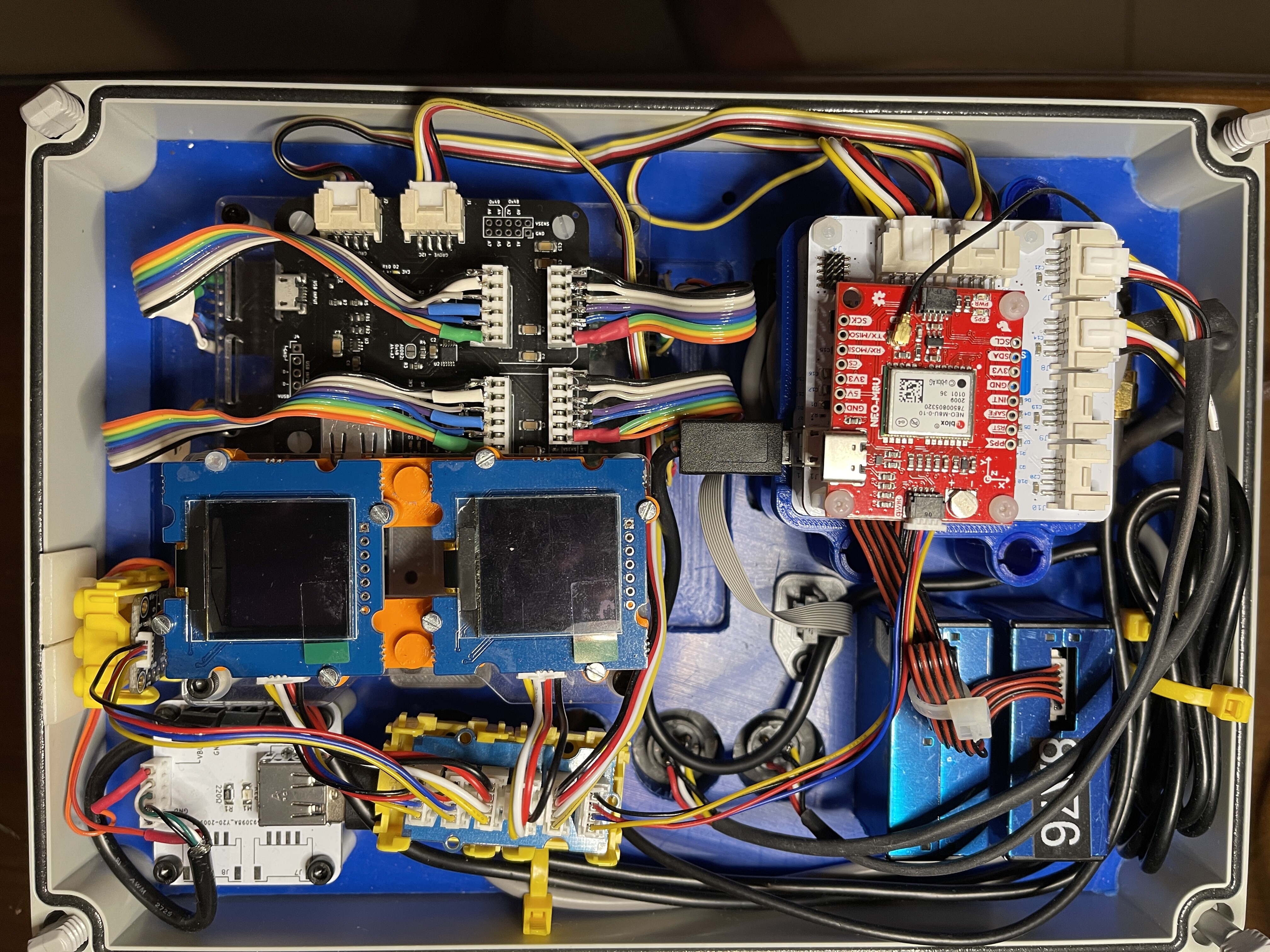
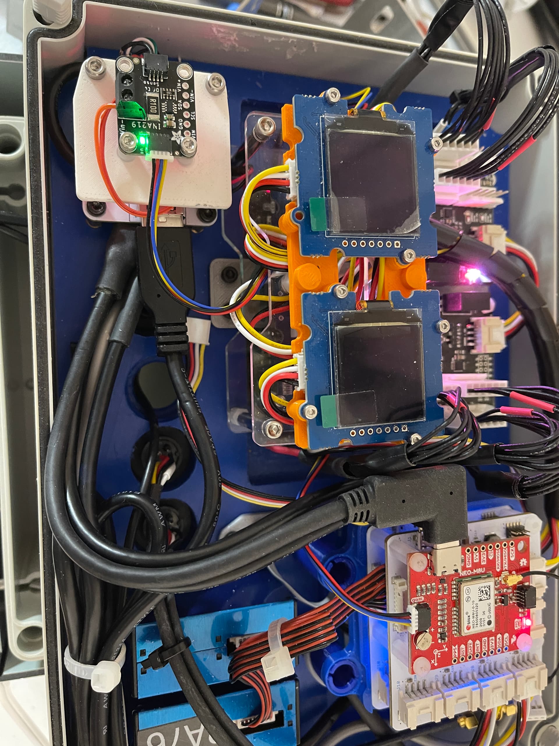
- NEO M8U GPS Board from Sparkfun.
- Additional SAMDG21 Board to handle the Wind and Rain sensors because there were insufficient Serial ports available on PM Board.
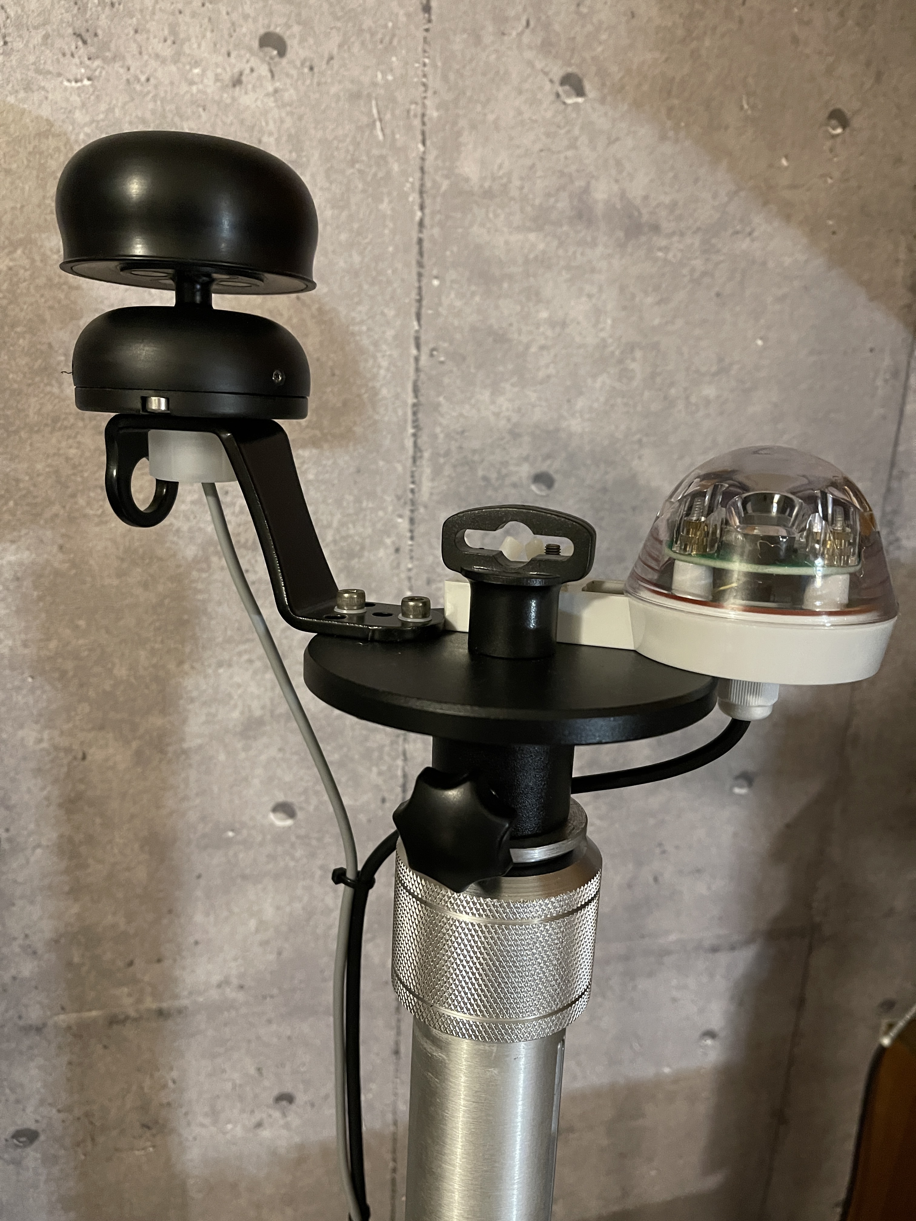
The Wind and Rain Sensors selected both have no moving parts; making them more robust in the remote mobile situation. They also have very low power consumption. - The Anemometer is made by Calypso Instruments (Spain) - their ULP model supporting polled serial connection at UART levels. It uses an ultrasonic technique to measure wind direction and speed.
- The Rain Gauge is the well-known Radeon RG15 supporting Serial Communication at UART levels. It uses Infra Red beams to measure rain drops deflecting the IR beam (by changing refractive index) on a transparent dome. It’s a similar principle used to automatically control windshield wipers on a Motor Vehicle.
- Communications: We add a Wi-Fi to 4G LTE gateway made by D-Link.
- Power: The extra sensors and the 4G LTE radio add considerable power drain to the system making battery power difficult but because the system is remote, battery power is essential. We added a 370 wH battery and 2 x 60 watts flexible solar panels made in Taiwan by Googol Company. It is physically large and heavy.
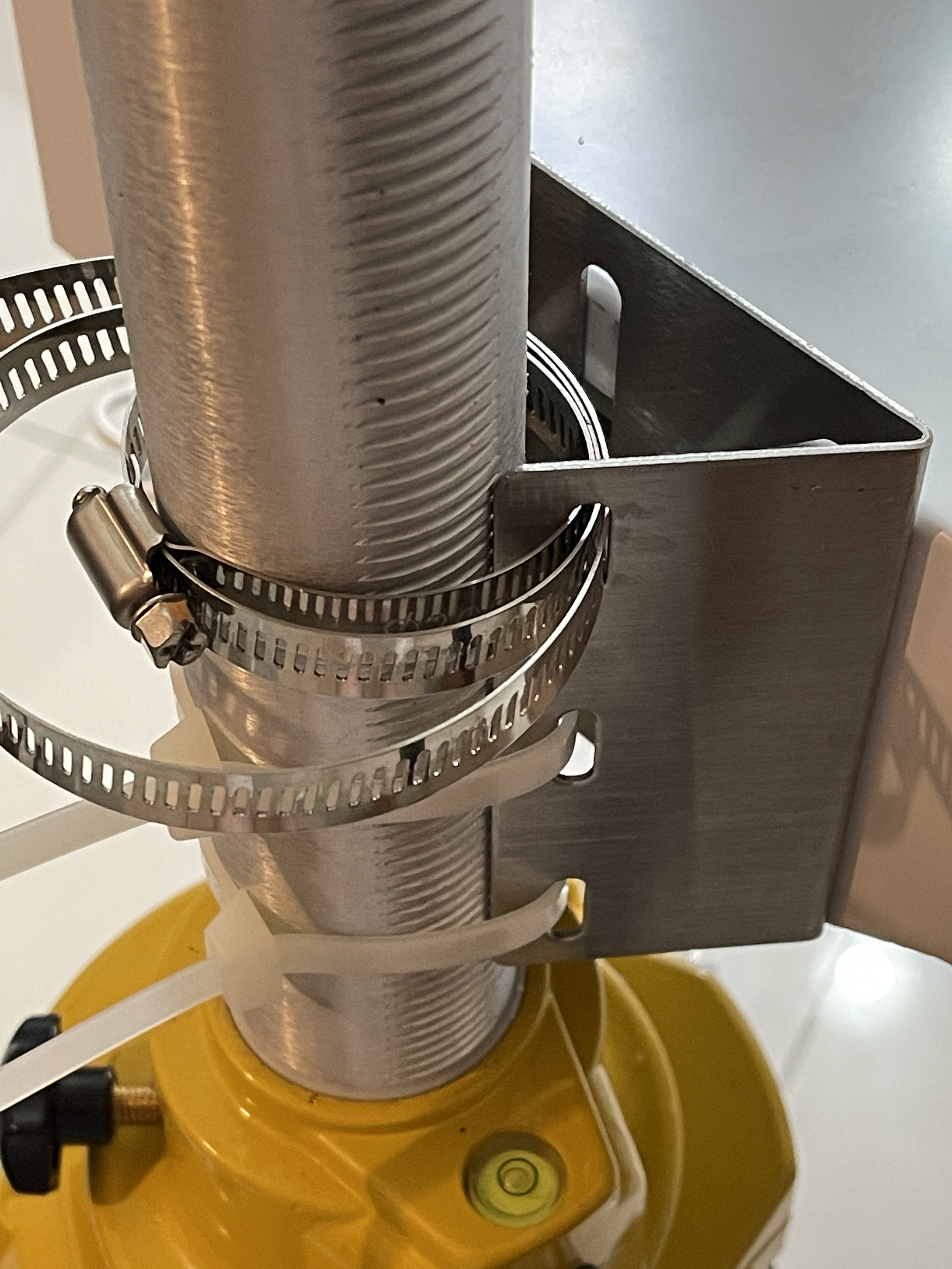
We also added a INA219 power measurement sensor to continually monitor power consumption. - Mounting: The system is mounted on a robust surveyor’s tripod that is made by Stabila (Germany & China) model BST-K-L
- Display(s). We added 2 x 128x128 Pixel Monochrome GROVE OLED V3 Displays from Seeed Studios for local output of readings and debug. They are turned off normally, but light up for a few minutes when a button is pressed
Conclusion:
It has so far taken several months to formulate the design of the system and gather all the parts. There were delays caused by COVID19. It will take some more time to complete firmware development and test the system.
Budget: This system no longer falls within the ‘inexpensive’ category of citizen science environment monitors such as SCK2.1; but it does prove that the basic Smart Citizen System can be extended beyond the limited capabilities usually found in commercial products; to form a more comprehensive type of monitor. Specifically the combination of toxic gas measurements, wind velocity and direction; Rain; GPS Position and Altitude are unique in the field of Environmental monitors. And because the Smart Citizen system is open-sourced, we know about every component, and we can closely examine (and change) the firmware; unlike a closed and copyrighted commercial system.
The comprehensive set of readings provide for interesting correlations to be observed, and for investigations to be carried out. For example we can now say things like “When the wind at this location X comes from the specific direction of Y, PM Dust levels increase along with SO2 levels, when there are dry conditions.”
Because the monitor system is mobile we can, using the one device, compare baseline readings from a pristine environment such as a National Park, with readings taken in an Urban environment such as a rooftop in an urban area; and the GPS data locks readings to a specific location.
One must carefully set expectations of the accuracy of readings from a Monitor such as this. Its not a highly accurate laboratory instrument. Price was part of the selection criteria for each type of sensor (although not exactly cheap in some cases).
Whilst each sensor is calibrated in the factory, and we take steps to calibrate readings ongoing for temperature and humidity effects and drift, one should NEVER make absolute statements about the accuracy of readings.
They are “best effort” within our budget. The readings will contain (relatively small ~~typically 10%) errors (indicated in manufacturers characterization data) that are consistent and there will be a stochastic element in each set of readings. One must use statistical techniques on each set of readings to confirm validity of any conclusions. But because the readings are taken at regular intervals with self-consistent error bars, the changes (delta) in environment characteristics over time remain reliable and valid.
The current status of this project:
Almost all hardware components have been assembled. Waiting only a couple of items.
Firmware development is started but not yet complete. When firmware development is complete details will be available via GitHUB as open source for the benefit of others wanting to do similar things.
Credits: I am indebted to the FabLabs Barcelona Team for their help in development of this system; in particular: Oscar Gonzalez (@oscgonfer ) has been my contact and mentor for the duration of this project and constructed the base SCS for this project.
Kudos: Both UPS and FedEx proved to provide excellent 5 star service all through this project, as did Digi-Key, Sparkfun and Mouser Electronics. We also like GW Instek a lot for making their wonderful MSO 2204EA Oscilloscope and great service.
Brickbats: I am unable to recommend: USPS, Deutsche Post DHL, Farnell group (Newark, Element14 etc.) (one star for each, with painful memories).
Interested in this project ? I am happy to field questions and encourage collaboration, comments and feedback concerning this project; within the constraints of time that I have available.