Back to Smartcitizen.me

[solved] No data outputed / PM sensor problem?

Hi,

I’ve just received my Smart Citizen sensor kit 2.1.
Thank you !

Unfortunately after flawless installation process, I see my kit on the website but no data are displayed.
According to the website, value are sent every minutes but the sensor values stay at “N/A”

I’ve succeeded in having some sensor data by unplugging the PM sensor. This PM sensor unplugged all other data sensors are well displayed (some weird value on ppm and TVOC but it seems to be normal at start).

Have you a workaround for this ? Thank you !

Kit registered with 9580 ID.

Hi @guillaume_smartcitiz

Thanks for posting here!

I suggest you unplug the battery and USB cable, plug the PM sensor and start the Kit again. No reconfiguration needed. If the problem keeps persisting write us back. Seeed checks all the board using a test plan we designed, but maybe there is a hardware issue it couldn’t spot, and your sensor needs to be replaced.

About the TVOC and eCO2, the sensor needs a long stabilization process. You can read more about it here.

We are working to improve the overall documentation on sensor stabilization, calibration and data awareness in general.

1 Like

Thank you for your quick answer !

Unfortunately I tried multiple time to unplug and plug back the PM sensor each time I have the same result:

  • without the PM sensor, sensors are started correctly
  • with the PM sensor plugged, all is disabled :frowning:

Although, the fan of the PM sensor does seems to start. I don’t know if it is normal or not.

Hi guillaume,

The kit try’s to autodetect which sensors are connected when it starts up, so the PM sensor must be connected before powering on the kit for it to be detected.

By this you mean that no sensor data is posted?
Can you please give me more details about the led state or anything else that you notice
Does the fan of the PM sensor is continually on?
Did you tried clicking the reset button after starting the kit with the PM sensor connected?

Sorry that i cannot help you more right now, maybe with more information we can find the issue.

Cheers!
Victor

Hi

Thank you for your help !

I always connect and disconnect the PM sensor when the device is off.

When PM is plugged, the board fade slowly blue for normal operation.

Website indicates that data are sent each minute but the sensors value are not updated.

Connecting to board serial console indicates all sensor disabled (except battery which is always “-1” as I don’t have one).

The PM fan is always off.

Bord reset doesn’t solve the issue.

When the PM sensor is unplugged all is working fine as expected (except PM values of course !)

EDIT: I’ve also tried once to activate the PM sensor through the console and it has lead to a board reset (and after reset all sensors still deactivated)

EDIT2: in fact the fan does power on for a short time at start-up

Thank you,

We’ll write SEEED to replace your sensor.

Hi,

I’ve received my new PM sensor ! Thank you a lot ! :ok_hand:

Unfortunately, it doesn’t solve the problem :frowning:

Same behavior, when PM is plugged, the board take time to start up : the LED goes green/white multiple time before fading blue. All sensor are disabled.
Except this time I didn’t see the PM fan moving even briefly.

When PM is unplugged, it starts quickly (green white then fading blue) all sensors are active (of course PM only output 0)

I’ve also checked the output voltage with my multimeter with the help of your schematics on github.
Vcc is 3.3V but +5V is 0,6V… :cry: (voltage tested with the urban shield unplugged)

Hi,

I’m sorry that it is not working.
Measuring the voltage is not that simple, because if the kit doesn’t detect a connected urban board it disables the sensors (also the 5v output) immediately.

You have two options:

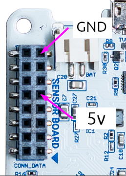
1. connect your multimeter directly to the data board on these pins:

image

And you need to manually force the kit to enable the sensor with a command through the serial console.
For this you need to connect your kit to the computer via USB and open a terminal (Arduino Serial Monitor, GNU Screen, or the one of your choice) here is a very good tutorial by Sparkfun that can help you in that mater.
After connecting to your kit with the multimeter on place run the command sensor -enable pm for two seconds you should be able to measure 5v, after that the kit will disable the power output again. Every time you issue the command the voltage should rise.

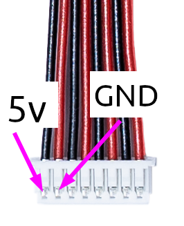
2. The other option (if you don’t want to mess with the console) is leaving the urban board and the PM sensor cable connected, but without the sensor itself. Put your multimeter on pins 1 and 2 of the cable:

image

Every time you reset the kit the voltage should rise to 5v and after two seconds slowly go down while the capacitors discharge.

Hope this helps!

1 Like

Thank you for your detailed answer !

I don’t know why but it now working !

What I’ve done:

  1. tested 5V without shield without power voltage: 0,7V (stable)
  2. short cut to discharge capacitor: voltage measured 0,0V
  3. plug power: voltage stay at 0,0V
  4. unplug power, plug shield and plug PM cable (without sensor) to measure voltage
  5. plug power 5V with slow discharge saw
  6. unplug power, plug PM sensor, plug back power : it is working !

It was not a connection problem (as I’ve tested it again and again.

Again big thank you for your help !

1 Like

I did find the root reason !

The issue was due to a not so great USB power supply.
The previous successful test was done on another USB charger and when I’m back to the original charger I can observe the same issue.

Sorry the problem was on my side.

1 Like

Don’t worry!
Congrats on finding the problem!

I am reviving this thread to share my own experience: the 2.1 SCK seems very very picky about USB power supply.
Actually, the USB charger sent with the kit works only with a short cable, when a 3 meters long cable is used, and with no battery, the behavior is exactly the same described by guillaume_smartcitiz.
I tried four different chargers, and was not able to obtain a regular operation: or the SCK keeps rebooting and does not update sensor data, or it remains forever in a idle state with fading blue led. I also measured USB voltage and it was always between 5.1 and 5.3 V, so I think that the problem is more underhand, maybe the added inductance due to the long cable causes a slow reaction to pulse current demand, with transient voltage drop not appreciated by the system.

All problems disappear if the kit battery is kept connected, both charged or not, with USB power supply. It, probably, assures a fast current supply helping the remote charger.

This is definitely a design weakness. :cry: SCK should be able to work with a reasonable range of input power supplies and cable lengths without all these oddities.

Maybe, a capacitor at the USB voltage input could solve the issue.

1 Like

Hi @nicola.pomaro

Thanks for sharing your experience. Definitively we will do some more tests and add your insights on to the documentation. As you said, having the battery always on is always the best solution.

It will be fantastic if you can share any ideas around the power supply circuitry design for the next revision. Here are the schematics:

https://github.com/fablabbcn/smartcitizen-kit-21/blob/master/hardware/SCK_DATA_BOARD_2.1/SCK_DATA_BOARD_2.1.pdf

1 Like

Hi @pral2a, Thank you for your answer and proposal. I will examine the schematics and the SCK power management.

I want to clarify that I am really impressed by this project, it is so powerful and flexible. I am discovering a lot on my home ambient, how daily activities, cooking, opening windows, cleaning, have an impact on air quality. A really useful tool.

Thanks for your compliments and your amazing tests, comments and posts!

@pral2a, I added an issue in https://github.com/fablabbcn/smartcitizen-kit-21/issues.

USB input capacitor could be increased actually, and, more important, it seems that a capacitor is lacking in the design.

Hi @nicola.pomaro

That information it’s extremely relevant. I will work together with @oscgonfer on updating the PCB and share you our thoughts!

Thank you!

Fine!

I am trying to figure the origin of that high pitch whistle during charging. It is not obvious as the components switching frequency is in the MHz range so nothing should be audible.