Hey everyone!
This post is dedicated to talk about the issues and fixes of the light sensor readings on the SCK2.1 that were found by many of you. There are only good news in this post, so don’t worry, it’s all under control! 
TL;DR
Below we will talk about the sensor working principle and the current readings implementation. If you want to skip the post, the good news are that it only takes a little firmware update in 3 steps:
Now, some interesting stuff about the light readings! The sensor in question is the ROHM Semiconductor BH1730FVC. It’s an I2C sensor with many applications, such as mobile phones, and LCD backlight adjustment in screens in general. It has quite a wide detection range, going up to 100klx (kilolux), and is able to distinguish between visible and infrared (IR from now on), and with some help from the datasheet linked above we are able to combine them both into a single reading. Very briefly, to understand these two readings: the visible component goes from red to purple and is what we see (duh) and the IR component has a lower frequency than red (and hence not visible to the human eye), and is able to heat things up by what we know thermal radiation. Most of the thermal radiation emitted by objects near room temperature is infrared.
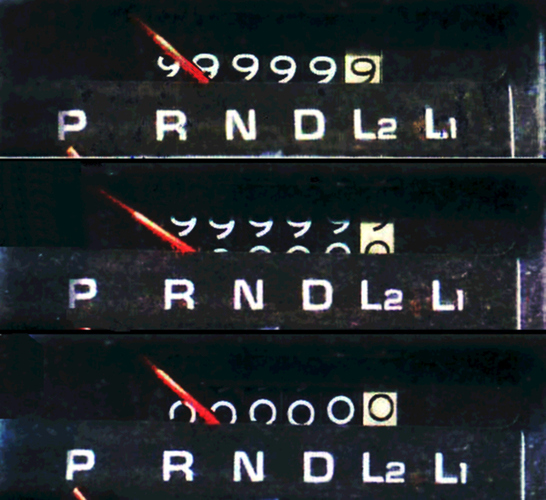
So, let’s stop praising the sensor and understand what was happening to make some you see this?
One single letter.
Long story short: the variable that was storing the visible component of the light reading was declared as int16_t, whereas it should have been uint16_t. For those who know about this, it means that the first variable was only able to store numbers from -32.768 to 32.768, while the second one ranges from 0 to 65.536. That’s why when the light was going above one certain threshold, it went down to zero. Also known as overflow.
But hey! That typo is gone. However, while trying to find this problem, we found out that sometimes, when the light sources are constant, the output of the sensor was going down  . By much. For instance, if we left the sensor under the sun, we could see an instant rise of the light reading, quite comparable to that of a luxometer. However, after 5-10s, the sensor reading decreased, with no aparent reason. This brings us to the next point. How the sensor was implemented and how we improved it’s reading.
As said above, the sensor reads both, the IR and visible components. In terms of implementation, and so that we can have a wider range, it has what is called integration time. This integration time is similar to the exposure of a camera. The longer the time, the more light the sensor will see and the best the accuracy we will have in low regions. On the contrary, for high light situations, as in the camera example, we want to have low integration times, so that the sensor doesn’t saturate (or make the picture look burnt).
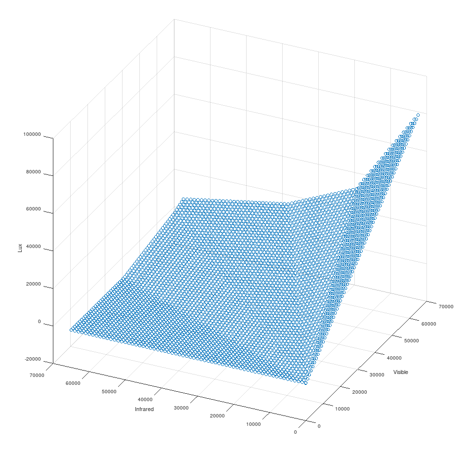
The sensor response to the IR and visible component is shown below:
On the z-axis of the graph you can see that, when we increase the visible component, the sensor reading in lx grows, but it’s not the case in the IR. In general, an increase of IR component will provoke a reduction in the light values, and this looks worse when the sensor is saturated in the visible range (right side of the graph). This graph was calculated with a normal integration time.
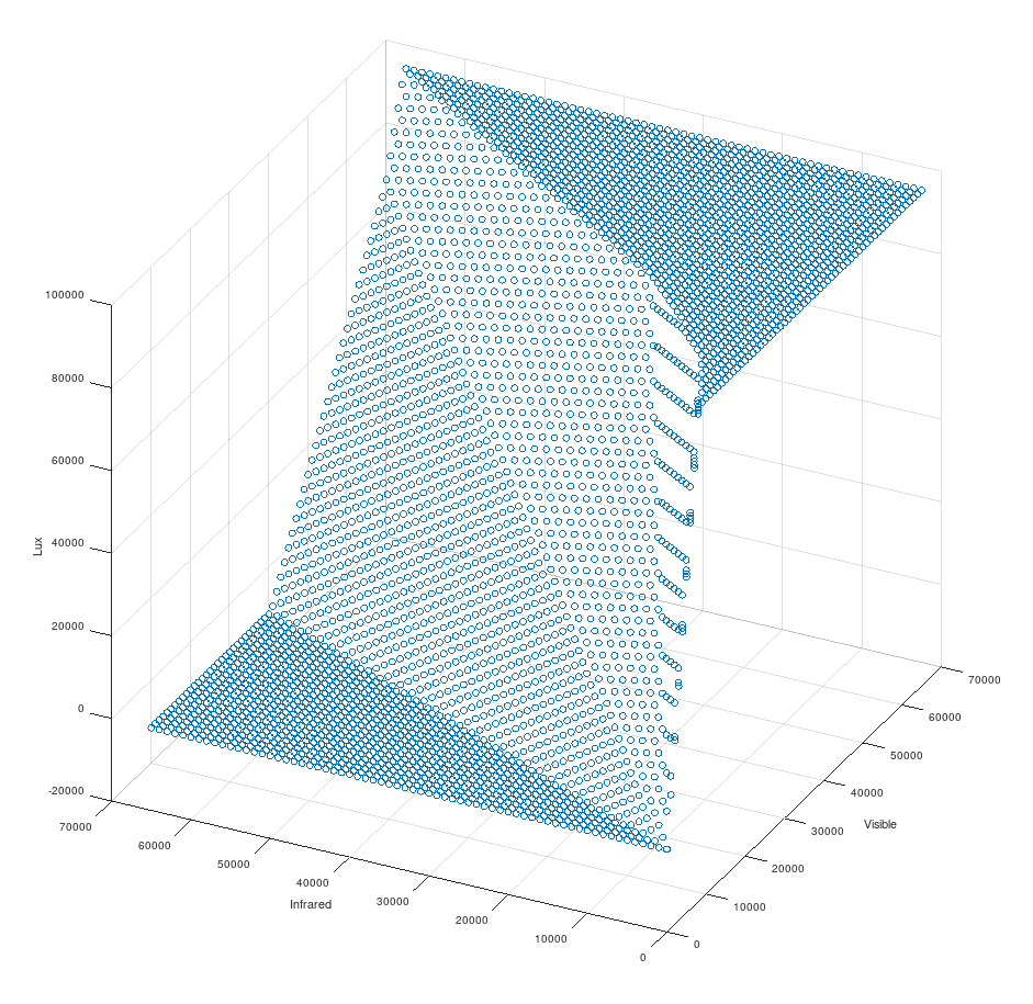
The maximum value from the sensor is 100klx, which is rightly matching the top right corner of the graph. However, with this graph, we might not be able to differentiate when we have a lot of light, or when we have a lot, a lot of light. For this, we thought that would be a good practice to reduce that integration time from before, when one of the components (normally the visible one) is saturated. In this case, our graph, limited to the 100klx from the datasheet, looks like:
Which helps us understand that, when we have a saturated value, we don’t want to mess around with lower values due to the infrared component. We just have a lot of light, and that’s it. And also, that we want to adapt our integration time, because in case of it being too short, a minimal amount of light will saturate our sensor and we won’t have nice smooth curves during the day.
So, to conclude, after a typo, a lot of boring stuff and some worries about the sanity of the kits, the light sensor issues can be fixed quickly and with little hassle. The fix is simple to apply (see above) and there is no problem with the light sensors hardware. We really hope this has been somehow explanatory and that you are able to upgrade your kits firmware and read the light sensors properly now! Apologies for the inconvenience!
Let us know in the comments below 
Happy sensing!


