Back to Smartcitizen.me

Building the firmware

Hi @bryn.parrott ,

You PMed me but I’ll respond here so that this can help others.
You mentioned that, as you state above, you’re having problems getting it to build SAM on your mac.

I’ll provide my notes but I have to say getting SAM building wasn’t too hard so this may not be much help:

I needed to set my path for pio correctly so that it uses the correct installation of serial.tools:

Note the order below - this caused me problems (for ESP but not SAM if I recall correctly but I may be wrong) (see here for more info):

export PATH="$PATH:/home/cyrille/.platformio/penv/bin"

Then I just built:

python make.py build sam -v

You should get/want a [SUCCESS] message.
There’s a bug where (noted somewhere) you may need to run the above twice to get the SUCCESS message.

I had to also update sam/platform.io to ‘point’ to the latest versions.

Unfortunately that’s it. Getting SAM to build was much easier than getting ESP to run because of my little path problem and serial.

1 Like

Thanks Cyrille for your response;

The fix you suggested is something I did right at the start.

I implemented the path addition in /etc/paths and it needed to be more explicit.
Before I made the change; “pio run” command would not work; after I made the change it worked; thus I consider it effective.

The issues I am finding have occurred during execution of the make file;
Two type of error:

  1. The make process appears to download only the latest version of libraries instead of the @ version specified including platformio.ini then it discovers it does not meet the @ specification and barfs. It does this on only two libraries; the MPL3115a library and the Sparkfun ublox gnss library.
  2. After that it finds problems finding parts of the Arduino platform library tools such as variant.h; there is also an issue with ‘hardwareserial.h’ found in both the Arduino distribution and the Radiohead library; causing a conflict.

I had similar issues when trying all of this on the windows10 platform; the reason I moved over to Mac platforms.

I am starting to think it ‘has it in fit me’ (lol). Or maybe I’m just stupid.

At this moment I am thinking possibly the underlying issue is the versions of tool chain files (Python ; Git; platformio) but that’s clutching at straws;
Potentially the fact that Apple include a version of python on the platform might be an issue; the latest python I installed must specifically be called using ‘python3’ on the command line.

Hi!
Yesterday we realize this was happening, we fix it on this commit please pull the new code and try again, hopefully this will help you!

Wow !

thanks for your help. I will ry it right away. Lets see if GitKraken is worth the money I paid for it.

also I found that I have two versions of Python installed:

When I execute the make script; I type: python3 ./make.py build sam -v
thus hoping to execute that latest Python3 version.

Please can you verify that:
a) Python 3.9.7 is optimal to execute the make file.
b) If a python command is executed within the makefile (or sub-scripts) that it will find the correct version (because /usr/local/bin is first on the $path)

These are my assumptions anyway; am I correct ?

Hi @vicor @oscgonfer

That change to platformio.ini did indeed fix the problem with getting correct versions of 3rd party libraries.

This leaves me with the next problem, see screenshot.
the make file is unable to locate ‘variant.h’ which is usually part of the distribution of arduino board packages etc. This file is referenced many times during the build, of which only one is depicted. This same problem was seen when I attempted the build process on the windows platform earlier.

Hi,
We have a PlatformIO custom board called sck2 that has its own variant files to define the different ports we use. Every time you build the SAM firmware a script is called that makes sure that the variant exists and hasn’t been overwritten, it uses the PlatformIO core_dir defined in the platformio.ini file.

I’m not sure, but it is possible that something related with what I have described doesn’t work properly in a Windows environment. Please check that you have this directory (.platformio) and that the board SCK exists in there (it should be in the same path mentioned before).

Hope this helps!
Victor

Thanks @victor for the pointer; I was aware that the folder existed; but not how it hangs together.

I checked; and found the sck2.json file within the ‘boards’ folder.
within the file it points to ‘frameworks’ keyword; with the value ‘arduino’ vis-a-vis:


The variants file is located under folder ‘framework-arduino-samd/variants’
Its probably a pretty dumb question and forgive me please for asking it;
Also I note that this file was last edited 13 months ago; and obviously its working on other platforms OK; but I wonder if maybe :
“frameworks”: [arduino]’ is really an alias for ‘frameworks-arduino-samd’
but otherwise I do not see how it could be that the variants.h file is to be found by the build system. Maybe its looking in the wrong place.
All I do know is that ‘delay.h’ wants it; and unable to find it:
.platformio/packages/framework-arduino-samd@1.8.9/cores/arduino/delay.h:23:10: fatal error: variant.h: No such file or directory. (7 times)

I remember from (many) years ago (vaguely) there was a diagnostic utility program available for developers under windows; its function was to monitor filesystem activity by a process; and log the files that it attempted to open or ‘touch’.
Do you happen to know if there is such a utility available for the MAC iOs environment that I coukd use to see where it is looking for ‘variant.h’ ?
That would be something like ‘fsmon’; {https://github.com/nowsecure/fsmon}
is it useful in this context ?

@victor @oscgonfer [ please read until the end of this message]
I tried installation of a tool called ‘fsmonitor’; It displayed a lot of information; but none of it useful to this purpose of discovering whether ‘variant.h’ is touched during compilation.

OK; So… I tried another pathway; (
I cleaned out the .pio and .platformio folders (except for framework-arduino-samd)

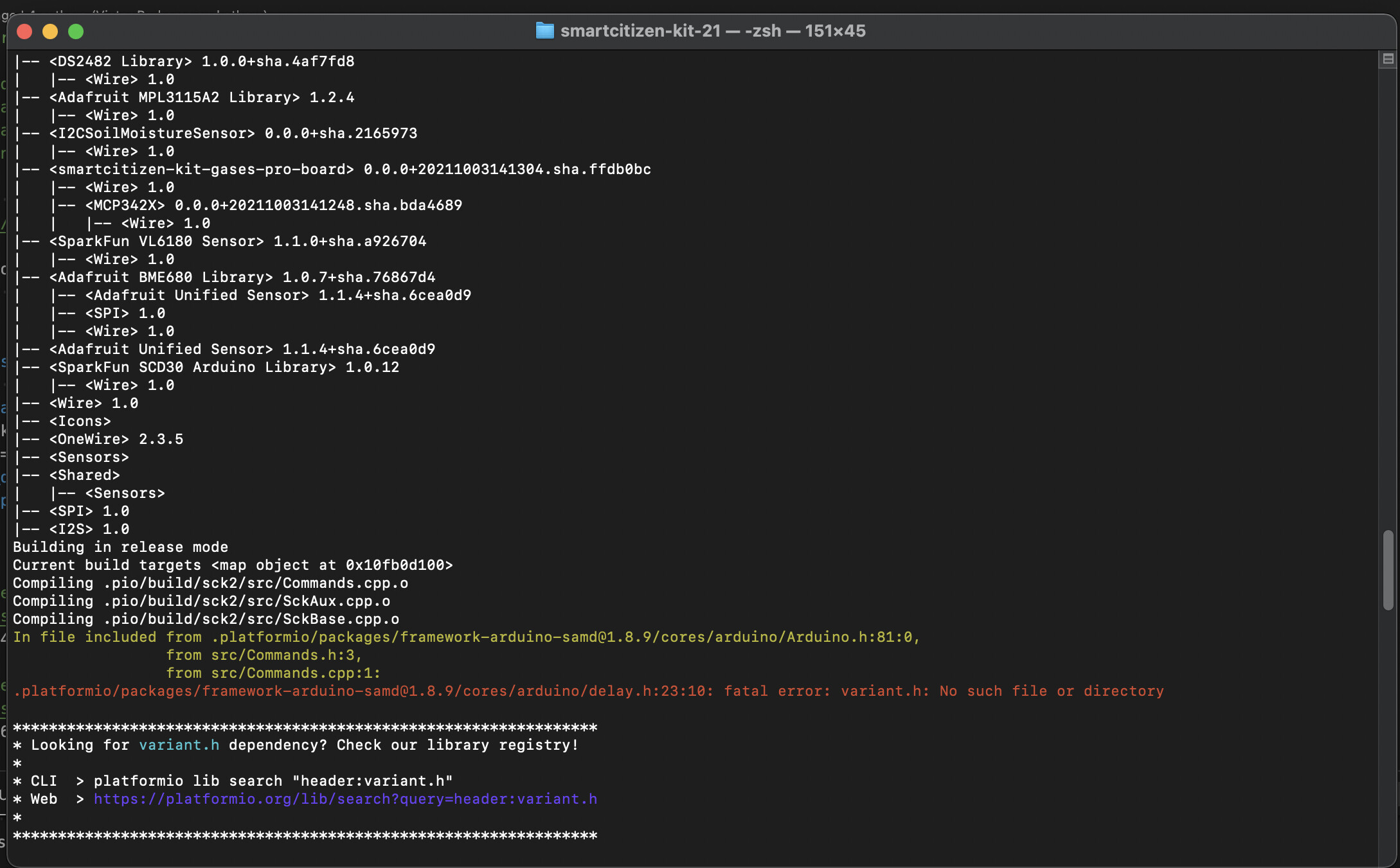
Then executed the make script. (and it got the same result as before - cannot find ‘variant.h’) (I am not surprised by this.)
then looked at the folders that were installed into .platformio

I notice that there are two folders for framework-arduino-samd.
one called framework-arduino-samd
the other called framework-arduino-samd@1.8.9

The difference between these two folders:(?)
- framework-arduino-samd@1.8.9 has ‘extras’ folder
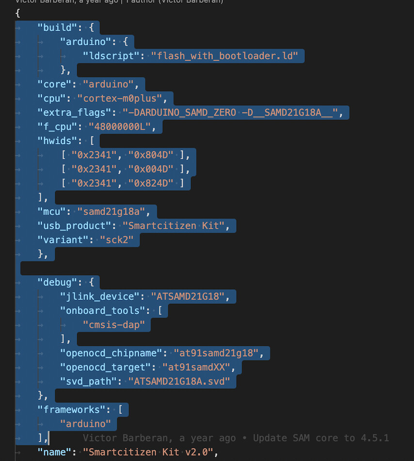
- it has variants folder that does not contain a sck2 fubfolder and hence no variant.h for the sck2

-framework-arduino-samd has:
- NO extras folder
- variants folder contains subfolder sck2

It seems possible that maybe the make process looks for ‘variant.h’ within the framework-arduino-samd@1.8.9 folder; and does not find the sck2 folder so it gives up ‘file not found’; But why are there two folders ?

So… I tried one more thing. I copied the folder ‘sck2’ from one folder to the other.

Then I ran the make file again. Here are the last two lines of output:

We found 197.04MB of unnecessary PlatformIO system data (temporary files, unnecessary packages, etc.).

Use pio system prune --dry-run to list them or pio system prune to save disk space.

Wrote 446976 bytes to /Users/brynparrott/Documents/Platformio/projects/smartcitizen-kit-21/bin/SAM_firmware.uf2.

.

Lo and behold; the make process has executed from beginning to end successfully.
It gave up a few warning messages; but completed and delivered a firmware file. I have no idea if it works or not. I will look into a few of the warning messages to see if they look important; before loading it into my scs data board.

For you to consider is the cause of this issue and whether and how to correct it.
Maybe it just needs a documentation fix (simplest) or …

@victor @oscgonfer

JFYI

I took the same learning over to my windows 10 PC.

I applied the fix you made to platformio.ini; however I found that when make.py is run; that I now get another different error; the script is unable to run the ‘sh’ command that would allow it to execute the git-rev.sh command script;
Now; It was previously able to do this (I do not know how); so I do not know what has changed to stop it from working. Since the ‘sh’ command never has existed on windows10 the make file must have a work-around; and that is no longer working .for some ungodly reason.

I checked the ‘pio run’ command and found that it also has the same issue.

At this stage; like you; I am inclined to just drop it; say that the build process does not always work on windows 10 and leave it. I have another option…

Bye the bye; I checked previous partial builds on windows; and found that the problem seen on the mac; namely that the folder ‘framework-arduino-samd’ is duplicated; not completely merged with framework-arduino-samd-1.x does not appear to occur when the windows build process can execute.

Congratulations!

In a clean clone of the repository in Linux, after building I only have the framework-arduino-samd not the framework-arduino-samd@1.8.9 folder. I don’t know why is different in Windows, when I have some spare time I will look into it and try to find a permanent solution.

To be sure everything works as expected you should also copy the second file (SAMD21_I2SDevice.h) indicated in this script. It fixes some problems with the I2S bus.

Cheers
Victor

Thanks @victor for the heads up on that file.

Next time I do a build I will check and make the change suggested.

@oscgonfer
Right now I have moved over to the physical task of wiring and final assembly, to be ready to “power up the beast”

This will entail online registration of the device; and I plan to connect via the 4G gateway wifi as well.

Also to this same end I have sent Oscar a link to a Google docs file that contains technical details of the Spec Sensors gas sensors. This includes:

  • sensitivity code,
  • serial numbers
  • I2C mapping for each of 5 gas sensors.
  • Temperature compensation data for calibrations

Of course I have only the 4 port ADC right now so one sensor (O3) will not function.
It’s looking like the 4 port ADC you included will be OK in fact I don’t see why you said I would find it unsatisfactory; unless of course it does not work. We will soon see I guess.

If it’s true then I am only short the one 2 port ADC and the box for the 4G gateway.
XxAnd a power cable for the 2nd PM Board…xx
Update: I purchased a micro-usb cable and cut it in half; made myself the power cable.

Meanwhile I will soon be able to power up and then load the firmware and start testing.

Cheers

Ok @victor @oscgonfer

The latest issue in this saga is that I am having trouble on MacBook Pro platform reliably recognizing the (2nd) PM Board plugged in for firmware loading and monitoring of debug.

The cable used to connect the PMB is a standard micro-usb meaning it has uUSB at one end & USB A at the other. There are no such ports on the MacBook; it’s connected using a dongle that plugs into both USB-c ports and provides 2x USBc and 2USBA ports.
I am thinking that this method of connection might be flawed perhaps the RTS/CTS or DTR signals that are needed to perform automatic reset of the PMB following firmware upload might not be getting through; thus causing the PMB not to behave correctly.
Secondly there is the issue I am unable to monitor SerialUSB debug stream to confirm correct firmware operation.
Thirdly it looks like firmware upload is occurring at default speed of 1200 baud rather than the set speed of 115200 baud.

The second problem is by far the biggest concern.

I went to local electronics shop and purchased several micro usb to usb-a cables and one usb-a to usb-c adapter; to try and eliminate the dongle from the equation. Unfortunately the one I bought usb-c plug is incorrect and does not securely plug into the MacBook.

So now; I am attempting to purchase a direct micro usb to usb-c cable hopefully with all the 8 wires connected through thus allowing rts/cts/dtr lines to pass through and perform reset when required.
This is not available in Taiwan in regular electronics shop; so it will need to purchase from US; some more delay. And I am in process of moving house which complicates deliveries.

Finally I looked at what is happening with the 10 pin connector: when I touch one pin with an open ended wire it seems to trigger a reset. I connected oscilloscope.
The thing I noticed there is quite a lot of random electrical noise in the environment even when GND wires are connected. I think that the open ended wire is acting like an antenna; and the signal is strong enough to trigger the reset.
Further to consider: the 10 pin connector is designed for use to connect the HWD device Atmel ICE or similar; on this same port on Data board; a ribbon cable is connected that goes to a reset button that is accessible from outside the enclosure.

I have in mind to borrow the reset button from the data board and connect it to PMB temporarily to use as reset. So the SCS will again need to be disassembled…(now that I finally got it all back together again….irony)

Also; I checked the firmware code and found some errors; re-implemented “pins.h” so that coloured leds can work and pin-naming for the two serial devices can be consistent.
But those bugs would not likely cause SerialUSB not to work for debug output.

So; I am thinking perhaps I should put together a simple Arduino sketch to establish that SerialUSB and reset function can work. Then work up to PMB firmware piece by piece. Back to basics….

You can see where I am going

If you have any suggestions on any of these items I would love to hear them; might save me some time.

Cheers

OK,

I went back to basics; I used Arduino IDE to build for the blink sketch; then elaborated to exercise the RGB LED. Then I added code to output debug on the ‘Serial’ port which did not work; changed it to ‘SerialUSB’ and the debug happened.

Arduino IDE was able to upload firmware and monitor the USB serial port in terminal window without any problem whatsoever.

So, then I moved the test code into the project folder and renamed the file “pm2_driver.ino” to pm2_driver.xxxino"; I also removed the manually configured port configuration from platformio.ini; and restarted VS Code.

I found that the file was built without any errors; and uploaded OK after a reset. I was even able to get it to monitor the serial output although it did not switch from upload mode to monitor mode quickly enough to catch the first few lines of output.
I tried the ‘reset’ button and found it does not work reliably; I am wondering if I have it connected in correct orientation. Lacking a plug location key; it can be connected in two ways;

So; I can go on now I think and try to debug the actual code;

@oscgonfer @victor

So now I have ordered an Atmel ICE debugging kit. Maybe its not essential; however I am sure that if I had ordered one in the past this issue could have been solved quicker.
I also ordered a I2C Driver from CrowdSupply which should be useful; in particular to help with testing correct functioning of the AUX I2C bus. (because) I have a concern there may be too much current being drawn from the I2C master (the Data Board).
I am not sure of what remedies are available if thats the case. I might need help from Oscar is it turns out to be the case. The main issue being that (I think) one or more Sensor boards have too low a value for pull-up resistors; but the value is not designed to be easily changed because they have SMD resistors and no jumpers.

Although its tempting to blame the tools e.g. PlatformIO, I feel its most likely that the main problem lies in my code; and my present target is the SerialPort definitions. I might be able to use Atmel Studio to investigate this more closely. I note PlatformIO can also work with Atmel ICE ; I am unsure what level of functionality it provides.

Getting back to the present issue; I am thinking (speculation) that my code has clobbered one of the lines associated with USB Port and the code on GPIO port has my laser sight guide on it. I do not have the time right now to look into this because I am shifting house and everything including the project kit must be packed up.

@oscgonfer @victor
OK; I have finished all the relevant unpacking, set up my new workspace and today is the first time I have been able to work on the SCS project in a few weeks, so I have a clear head.

I determined first to recheck my work on assignment of the sercom ports for the Anemometer and Rain Gauge.
I started with the Microchip Documentation for SAM D21/DA1 Family; looking specifically on the big table of PIN Multiplex on Pages 30-31.
I made a reduced list of all the pins and which sercoms & pads could be assigned to them.
I then moved to the circuit diagrams and determined which PINS are wired out to which physical ports.
Finally I looked at ‘PINS.h’ file in the repository code; plus ‘variants.h’ in order to determine which sercoms are actually used by all 6 serial ports.
I have the following (check me):
Sercom 5: (Pins 31,32) I2C
Sercom 4: (Unused)
Sercom 3: (Pins 33, 34) USB Port
Sercom 2: (unused on 2nd PM Board) (PMS socket A)
Sercom 1: (Pins 45,46) SWD Port AND (Pins 27,28) Uart Port.
Sercom 0: (unused on 2nd PM Board) PMS Socket B)

Along the way; I discovered one possible reason why I have made errors in the port assignments:
In the PINS.h file we see entries like:

// RGB Led pins
const uint8_t pinRED 	= 26;		// PA27
const uint8_t pinGREEN 	= 25;		// PB3
const uint8_t pinBLUE 	= 13;		// PA17

Now, I had assumed that the {label = number} correspond to physical pin numbers on the SAM; but my assumption appears incorrect.
The coloured LED wires are (according to the circuit diagram) are connected on PINS 48, 39 & 26 corresponding to Ports PB3, PB23 & PA17 ; So it looks to me like either the circuit diagram or the PINS.H file are incorrect.
And yet the code works (for the first PM Board) !!
Please can you enlighten me on what is going on here !!

My current proposed solution is to use the following assignment:
“ADC” port ADC0 & ADC 1 Pins 9,10; Ports PA4, PA5 assigned to Sercom 0 (ALT) Pads 0 & 1
and
“GPIO” port GPIO0 and GPIO1 Pins 21,22 ports PA12, PA13 assigned to Sercom 4 (alt) Pads 0 & 1.

This I hope will ensure that SWD port will remain available and no existing port will be ‘clobbered’ by my code.
It seems to me ironic that I am unable to actually use the designated UART port because sercom1 is used by SWD and sercom3 is used by USB and those are the only two sercoms that could work on PINS 27/28 PA18/PA19
I grant that some of the issue might be mine; that I do not know how to implement sharing of the sercom pots.

Anyway; I am proceeding. I will make the required code changes for this; also look at the issue advised by @victor a few weeks ago concerning the variants file. This first part of this will be to create a ‘clean’ working code base.

Cheers

Ok; after a long delay today I sat down to go through the issue and determine the facts.
The problem is that when my firmware is uploaded to the PM Board the USB port gets blatted and debug output sent to the port cannot be viewed. Furthermore the MacBook recognition of the port evaporates and I have to go through a tedious procedure to get it recognized again.

I attached an oscilloscope with 8 input logic probe to each of the two active wires on each grove port (4) for a total of 8. Attached photo shows test setup.

I developed a sketch in Arduino that pulsed each pin high as an output; using initially using the pin outs (numbers) shown on the circuit diagram. I noticed that only one of the 8 pins actually produced anything.

Then I changed the sketch to use the original pin outs described in the file ‘pins.h’ which forms part of the firmware code for the first pm board. I observed that the PIN numbers were markedly different than shown on the circuit diagram.

This test verified that the original pm board pinouts in ‘pins.h’ for GPIO; UART; ADC0 And ADC are all correct. Also the pinouts for the coloured LED were verified at the same time.

By making appropriate changes to my firmware code for the 2nd pm board; the anemometer and rain gauge now stand a reasonable chance of working….

I have entered a bug report on the circuit diagram PM Board Sheet 1. It should match the facts and evidently does not. It is misleading….
Attached picture Also shows my stand-in for a reset button (a jumper lead).
I randomly observed that when the RED lead for the 3 color LED is set low; the led illuminates only briefly; whereas GREEN AND BLUE both illuminate for the same time period.

@oscgonfer @victor
OK; so here is the latest iteration:

I am rebuilding the PM Board firmware line by line; thus to discover which part of the code causes the PM Board && USB port to hang up after uploading the firmware binary.

I am using an oscilloscope logic probe connected on the grove connectors.

The issue I am finding today:
The Grove connector has 2 signal wires; Yellow on Pin 1 (Rx); White on Pin 2. (Tx)

Now; what I find is that no matter how I define the pins and uart port declaration;
the GPIO Connector has TX output on the yellow wire and the Uart connector has TX on the white connector. Neither of them respond to code changes that ‘should’ switch TX and RX around. I need them to be consistent; because I am using standard wiring to the two external devices; which obviously want TX on a specific wire; and RX on the other. I could fix the problem using my soldering iron; but it would mess the colour coding of the wires.
Here is the coding:

// Hardware Serial UART GroveGPIO (Grove #3 on PM Board) (9600 - Rain)
Uart SerialGroveGPIO(&sercom4,GPIO0,GPIO1,SERCOM_RX_PAD_1,UART_TX_PAD_0);
void SERCOM4_Handler() {
SerialGroveGPIO.IrqHandler();
}

extern Uart SerialGrove;
// Hardware Serial UART SerialGrove (Grove #4 on PM Board) (38400 - Wind)
Uart SerialGrove(&sercom1, RX0, TX0, SERCOM_RX_PAD_3, UART_TX_PAD_2);
void SERCOM1_Handler() {
SerialGrove.IrqHandler();
}

If either of you can shed light on this strange behaviour; please let me know; however I will be otherwise be forced to switch physical wires (on GPIO socket) in order to proceed.

I am have looked into sercom.h and a few other library files to see if they shed any light on this. However they did not. I am left with the conclusion that:
a) the physical pins on the connector have fixed TX/RX capabilities conferred by the MUX.
b) the physical pins for RX and TX on GPIO Grove connector are swapped relative to the Grove Standard. This is a PCB layout design issue. Not possible to correct it without redesign of the board; unfeasible.
c) therefore my only option is to do the unthinkable; which is alter the wiring at some point on the pathway to one of the devices. This will tie each device to a specific port. The sockets leading to each device must be labelled. Its nothing new; because the port used for a device is determined in firmware code.

@oscgonfer
Today I modified the wiring as indicated earlier; switching Tx and Rx leads on the grove cable from GPIO intended to connect to the Rain Gauge.
Then; to verify integrity of the wiring; I connected Logic Analyser to the sockets to confirm Tx signal appears on the same pins on each socket. I also monitored the Rx pin of each socket. Logic probe GND is connected to Board GND.

I noticed spurious pulses appearing on the RX lead of the GPIO socket.

To investigate further; I connected the analog oscilloscope leads (Its a MIXED SIGNAL Oscilloscope) to the Rx leads. This allows me to inspect the signals in both digital domain and analog domain.

See attached photos.
Key to photos:
Upper part of the screen:
Logic Probe leads are indicated on left of the screen; LP Lead 0 is Rx of GPIO; LP Lead 1 is Tx and Oscilloscope Port 2 is connected to Rx.
Lower part of the screen:
LP Lead 2 is Rx of UART; LP Lead 3 is Tx. Oscilloscope Port 1 is connected to Rx.

Triggering is on Osc Port 2.

You can see that Osc Port 2 displays a 100 mV P-P spurious signal corresponding to the Tx signal LP Lead 1
Osc Port 1 displays a 100 mV P-P spurious signal that corresponds to the Tx signal LP Lead 3
This looks like crosstalk to me.

In fact the 100 mV signals show short peaks up to 200 mV.

Now; the Rx Leads are unterminated in both cases. the noise comes from induction/capacitance on the150 mm Grove Cable inside case + PCB track on PM Board + additional 150 mm ribbon cable for pinned measurement probes.
When the two devices are connected; no doubt the leads will be terminated with some unknown impedance.
The ~1.5 metre cables leading to the devices are unshielded. No doubt a greater amount of induction will occur due to the increased length; increasing the degree of crosstalk.
The question is; do you think I need to be concerned about the induced noise signal at this stage ?

Thks; Cheers,
Bryn


@oscgonfer @victor

Ok today is a milestone day; having completed debugging of the 2nd PM board up to the point of needing to connect the system together and start to communicate using I2C. Both the wind and rain sensors are connected and responding as expected to polling commands. They are connected to GPIO and UART grove ports; without interference with other serial ports including the USB. I am able to monitor usb debug output right away after uploading code.

The two devices are read independent of I2C requests. The loop method just performs a reading on each device every X seconds and stores readings in an array. When I2C reading request occurs the code simply reads the array values. This method avoids having a delay (to perform a reading at low data rate) when I2C requests a reading. A response will be returned immediately thus minimising overall system latency.

An internal simulation of I2C bus commands indicates that readings should be returned when requested.
Spurious pulses seen on receive wires earlier seem not to be causing an issue; I assume this is because devices now connected provide a termination and the wiring does not pick up the spurious crosstalk signals.
However the Rain gauge does seem to transmit spurious characters during initialisation; I have been forced to set up a ‘retry’ loop on the ‘begin’ method for this device.

Ultimately all of the bugs causing Usb lockup I found were in my code; but I still hold the view that pin numbering shown on the circuit diagram ought to match what’s seen in the code. The circuit diagram pin numbering matches the Atmel documentation but the code doesn’t work if I use the documented PIN numbers. So at some stage I would appreciate an explanation of how and why this has to be the case.
BTW The oscilloscope I have turned out to be indispensable in identifying bugs and verifying fixed issues.

Connecting the system together will entail first bringing the data board online with wifi, registering it etc so that the data board can do its thing and all should work. This will initially be done using Unmodified 0.9.8 firmware and only the standard devices connected on the I2C bus. This is to verify I have not broken anything before diving into attachment of the new sensors one by one. And then I can introduce code modifications that include integration of new sensors.

I have assigned I2C address 0x12 to the second pm board; It is not a reserved address and I have seen it used in Atmel example code.

About now it would be handy to have on hand the newADC boards; allowing me to complete physical mounting operations before wrapping up the assembly project and concentrating solely on the firmware…… oscar tells me the boards are nearly ready but with some issue on auto-recognition. I hope the boards can be sent soon enough.

I anticipate issues when adding the devices onto the I2C bus; because one device has a set of pull-up resistors with a lower value than the standard 10Kohms used on this system. This lower value will push the current on the signal wires over the I2C specification tolerance limit. So I bought a device that’s tailor made to monitor the I2C bus. It’s a kickstarter crowd funded type thing. This will help to verify when an I2C issue arises.

1 Like

My elation from yesterday was short-lived. Today I am back to one step forward; two steps back mode.

The task at hand is to turn on the main SCS system; attach it to Wifi and generally get it working.
However a number of snags came up during this process.

  1. Device attached to USB and Arduino terminal connected. Press reset on the kit (external reset button). The terminal informed me that it was enabling various sensors. It found an urban board and it went about enabling th sensors thereon. But it failed to detect the CCS811 (and Dust Sensor; which is not connected). It did not deliver a SCK> prompt.
  2. I followed common sense fault finding procedure and proceeded to disassemble the kit from the SCS enclosure. I quickly found a tiny gap on the connector between Urban Board and Data Board. It was wide enough to slightly show the shiny pins of the connector. But it looked like it should have worked. Diagnosis: the Urban board was slightly unseated. I fixed that problem and then powered up the kit again. This second time the UI indicated that the CCS811 was found and the system was able to complete its startup; and a SCK> prompt followed.
    I note that this experience reflects the experience of several other users, and I always get them to check this connection.

*I immediately have the idea that it would be good to fabricate a little plastic clip that can be used to secure the urban board onto the data board so they cannot come adrift. Particularly the SCS has the urban board buried deep within the enclosure, it is hard to get at; and its necessary to disassemble the system to check it. I agree that the data board is fully secured with those 4 big screws, and they should also serve to hold the urban board in place; but this above experience suggests otherwise. *

  1. I was able to run through a series of UI commands indicating that the system appeared normal; although of course, many sensors are not found because the Aux bus is not connected at this time.
  2. I decided to run through the onboarding process. This ran into trouble due to a non-cooperative WiFi - 4G adaptor. The battery was flat. The Gateway WiFi network was not visible in the list of available networks. I had to abort part the way through. Even when the Wifi Device came on line I was unable to get the SSID to appear in the list…
  3. I decided to try the SD Card procedure and this also ran into trouble. I removed the SD Card and checked it using the Mac computer. This showed several files on the card, among them an info file. I opened it and it informed me that the firmware versions are 0.9.7 for the SAM; and 0.9.2 for the ESP. So, I think that I will need to perform the firmware update process before I do anything else.[ I have to say I had assumed 0.9.8 firmware would already be in place when the SCS was sent to me. ]

So thats what I am doing; will update this message as I proceed until the job is completed.

  1. OK; so I was able to update the firmware. I was able to update the SAM firmware OK using my Mac; but not able to update ESP Firmware the same way. This was because the button that would allow browsing for the firmware file did not bring up a Finder dialog on the Mac Nothing happened.
    So, after some messing around; I was able to install the SAM firmware using my iPhone. That was also problematic because I was using Chrome, having extra security, and it wasn’t easy to find the downloaded esp firmware file when it came to upload.

  2. OK, with new firmware now in both processors; I can see that the basic SCK part of the SCS is online and publishing data. So, I checked the smartcitizen website using my old login; and find that there appears to be no way for me to enter the credentials to add the kit to my logon.
    I will send you a PM with the details; please can you join kit to my login. Thankx :slight_smile:

  3. I now connect the PM board to the Aux line, and also the power connector for PM Board.

I am wondering how much further I should go connecting additional aux bus devices with Mac usb as the only power source. The current drain indicator on the Mac System Information screen shows 500 mA being drawn from the connector; I wonder if it is a true indication or not.
If I need to provide additional power then I wonder how I can draw power through the SCS power supply whilst continuing to monitor activity via usb ( they use the same usb connector)
Can I have data board powered from Mac usb (direct connection) whilst the rest of the system gets power from the SCS power supply ?

In any case with this (Mac usb power source) arrangement in place I find that the PMB; two PM sensors and Dallas temp sensor are all found on the aux bus and readings start to be sent to the server.
All good so far.