
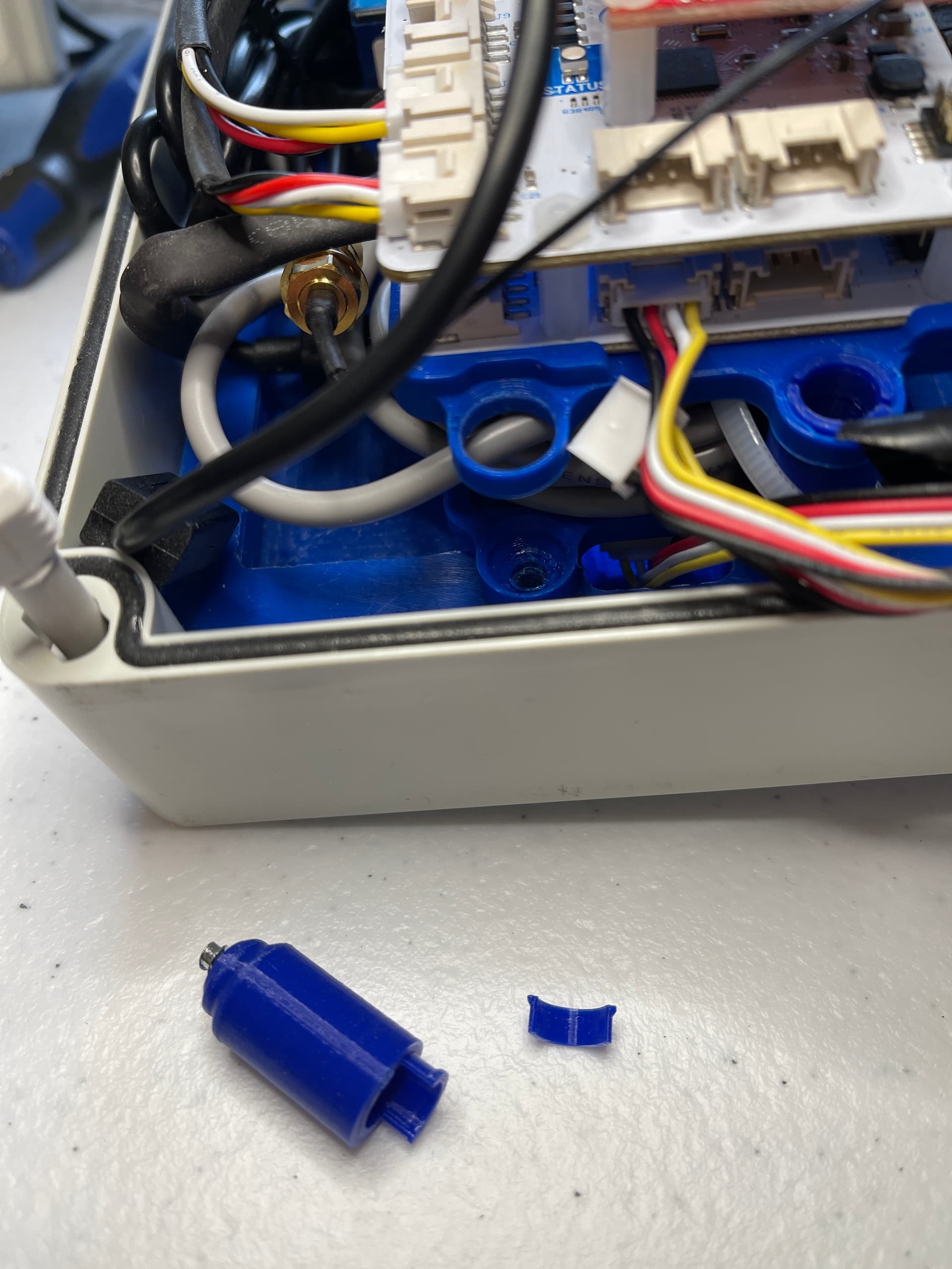
Ok in re-assembling the SCS I managed to break off one of the 4 3D printer screw fixtures designed to hold the frame for PMB and securing the data board.
I am of two minds as to whether to ask you to send me another; I could try gluing it back together or just leave it off; since the assembly seems secure for now. One possibility is to request the 3D print files for the frame and screw holder so I can later make my own when I one day get my own 3D machine. I am not going to allow this to hold me up for now.
OK, so I have started the process of checking out the SCS system, with Aux bus connected.
Starting from the point where I have established that SCK2.0 part of the system is operating as expected.
I monitor the system using UI; using ‘Serial Tools’ app.
Actions and observations:
-
I connect the AUX line to PM Board 1; which has 2 dust sensors; Dallas temp probe; and nothing else connected. I find it necessary to restart the system using reset button, LED is White.
I find that the 2 PM Boards are found, plus the Dallas Probe. -
I connect OLED display to PM Board; and reboot; I find that the system hangs
-
I try other devices connected to PM Board; the system also hangs.
-
At this point I connect the I2CDriver system. It has 3 x I2C connectors. Conn 1 goes to Data Board Aux Line; Conn2 goes to PM Board; Conn3 goes to downline devices. The device is supplied 5V via USB Connection to the MAC. I check that the voltage applied to I2C bus is 3.23 V. I note I2CDriver user manual indicates the device derives its own I2C voltage from its own 5V supply. It does not draw from the I2C voltage rail; rather it supplies the voltage to other devices.
-
When I connect to OLED Display and reboot; I find that the OLED is detected and initial graphic appears on the display. Later, it begins to display different sensor readings at about 10 second intervals. Evidently this is now working. Current consumption displayed. I form the hypothesis that the reason OLED did not work when initially connected to the PM Board direct might be because the PM Board cannot supply sufficient current; but the I2C driver can.
-
With ICDriver in circuit I am able to connect (a) ADC Board and (b) INA219; (c) GPS;
I find that : Current draw from the 5 V supply of I2C driver is now around 160 mA.
(a) ADC Board does not give up any readings. Appears non-operational (giving NULL Readings on all 8 inputs) despite the fact it displays two LED’s, one white, the other red. This requires further checking. I need to verify that the connectors going to Gas sensor board are correctly oriented and have correct supply voltage.
(b) INA219 is identified as an active I2C device, but it does not yield any readings; does not get recognised and enabled during boot-up. HypothesIs: Some issue with the firmware ?
(c) GPS is recognised. Initially gives up Null readings; but I already know this devices requires some time to download ephemeris ad get first fix. After a suitable delay it finds 32 satellites, gets a fix from 20 of them, and achieves HDOP value of 1 (a Good fix). However Longitude shows as a value of 0. I will need to monitor this for a while to see if the location vectors normalise. This could be a device issue or it could be a firmware issue. -
A little later I recheck everything using the UI.
I find the unusual status that whilst OLED, ADC, GPS, (but not INA219) found on the bus and enabled; when I perform I2C command only one (PM Board) device is found on the bus. Later I recheck and it finds 0 devices. Another Hypothesis: perhaps the I2C driver is affecting the transmission of I2c data from port to port ; affecting the ability of data board to detect aux bus devices.
so, there are a few mysteries floating around in here, I have some more investigation to do.
Ok today’s update.
- Issue with 5v sent the gas sensors instead of 3.3 v:
I tried to obtain a viewer for .sch files found in the repository for ‘gas sensor’ board. In turn; I installed ‘Autodesk Eagle’ (which did not open the file)
Then Autodesk Fusion 360 free version for personal use (which did not open the file)
Then Freecad and an add on tool for Kicad; and
- Freecad could not open the sch file
nor the Kicad tool could open the Kicad sch file.
So I am thwarted in my attempt to see if it’s possible to get the Gasses ADC board to put out 3.3 bolts on the 4 x 8 way gas sensor connectors.
So I gave up and continue to hope that @oscgonfer can come up with a solution; particularly as he has been working on sending me replacement ADC boards.
- Removal of I2C driver and health of Aux I2C bus.
- I removed the I2Cdriver connections.
- I connected PM Board #2 to pm board #1 (I2C)
- I powered PM board 2 via the power distribution board usb connection.
- I connected GPS, INA219, SCD41 to PM Board 2
—- at this stage found that SCS boots up ok but the GOS power light does not illuminate. - I added a USB power lead to the GPS usb connector.
—- now I find that when SCS boots it find the gps and it starts working; and it also finds the other two devices on the bus. - then I connect the ADC Board; and find that it lights up. A reset of SCS now shows the ADC board recognised and the other two devices.
—- now I try to connect OLED to the I2C bus 6 way connector. When I reset the SCS no devices are found on the I2C bus.
—- then I connect OLED to 2nd I2C port on ADC board. When I reset the SCS the OLED lights up; the ADC lights up. SCS finds INA219; SCD40; GPS; oled; but not the 2 x ADC addresses on the I2C scan.
Strange.
My conclusion is that the low value if of pull-up resistors in the OLED display kill the I2C bus. However there is enough power supplied by the grove wires to actually drive the display.
Luckily, in normal use; the OLED is not required so this could be sacrificed to get the project up and running; but I am challenged by what I see and would like to find if there is a way to correct the pull-up resistance issue on this device. @oscgonfer at one stage said this could be done; so maybe he can help here too; however I will try Google to see if a search yields any useful information.
As a secondary issue; it’s a little frustrating that the INA219 steadfastly refuses to work. It is supposed to be supported in firmware code. So I will do a little more research to try and find out why it’s not working.
These are the files! smartcitizen-enclosures/tubito-4x.stl at master · fablabbcn/smartcitizen-enclosures · GitHub
Thank you for sending me the link.
I have not yet ordered my Prusa although my mind is made up to get one. If I order one now It will be January before I see it.
Although it’s a small part, This might be a good excuse to open the wallet….
Getting back to the topic. I have ordered a couple of Seeed’s 8 channel I2C multiplex units, in order to see if that’s a pathway to having a more reliable operation of the I2C aux bus. In particular addressing the issue whereby OLED seems to kill the bus. I assume this to be caused by pull-up resistors too low value; increasing current on the two I2C signal wires beyond the 3mA limit.
The mux unit; at the very least will add a buffer on the bus.
I note however that the 8 channel mux unit also has 4.7 k-ohm pull-ups, but I am hoping that judicious arrangement of downstream units will make that less of a problem. Or maybe this device will allow the pull-ups to be removed from circuit.
Mounting of this unit (if it’s successful) will present a challenge. I am hoping it might fit in the same mount points as the 6 way grove hub it would replace. It’s 80 mm long; the 6 way is 40 mm….
The strategy for using the I2C mux unit:
Todays problem is that when I connect all of the aux bus sensors etc the data board cannot detect all of them. Implying that the I2C signal is degraded; and calculations indicate it’s likely because I/C signal line current exceeds specification; too much current through the usart tx/Rx interface transistor.
A max unit switch will allow the aux bus to be split into segments; connect each device to one port and only enable one port at a time; thus not causing the above problem.
So the deployment plan involves taking the main data board firmware and applying the library code for the much unit. It’s very simple code that appears to put a wrapper around the standard wire library. It’s applied to I2C interface; thus every device on that bus must go through the mux. But no special code needs to be added apart from:
- the change to wire library declaration and adding initialisation code for the mux.
- I may also need to change the i2c device discovery function to support the mux. I’ll look at that code and decide
Adding this code should add minimal amount to the firmware memory footprint; but it should be checked along with other tests.
Only when I am satisfied that this part is working and stable should I start integration of new sensors.
There are other issues with I2c mux:
-
Physical size of the mux is 100% longer (80mm) than the 6 port seeed multi-way grove connector (40mm) it replaces. @oscgonfer has just sent me new mounting to suit the 6 way grove. It’s almost arrived.
I am hoping it might still be able to use the new mounting; I will soon see, I guess. -
Power supply to sensors.
- The gps unit will be powered from usb socket
- The 3 x Adc boards powered from Grove aux bus
- Pm board 1 & 2 powered from usb
- The OLED x2, ina219, scd41 all powered from grove aux bus.
My understanding is that the grove aux bus is supplied 3.3 v from connected 5v usb powered devices : data board, pm board x 2, and gps.
I am uncertain what the max supply current for each of those devices is. I assume that the 4 x 3.3 v sources are effectively in parallel and able to supply some current to unpowered sensors connected to the bus eg. shared. I will need to check the voltage and current drawn from the aggregate grove supply lines when I have the max unit in hand.
Whilst the operation of the signal leads through the mux seems clear enough it is unclear how the Vcc and Gnd power leads in the grove connectors pass through.
This is something I will need to check out.
Yesterday I received Replacement ADC Boards from Fablabs.(Thanks @oscgonfer )
I have several tasks in front of me In pursuit of my intermediate goal to connect Spec Sensors gas sensors to my SCS V3 system.
The Analog to Digital Conversion boards serve the function to convert tiny analog voltages output from each Gas Sensor interface board into a binary number that is sent to the SCS MCU core over the I2C communication channel.
The first step is to set the correct I2C addresses for the second ADC board.
Context: The ADS1x15 chips can each have one of 4 different addresses. (0x48,49,4A,4B)
Each of the SCS V3 ADC Boards has 2 x ADS1x15 set to 0x48 and 0x49 by default. There are 5 solder pads on the board adjacent to one of the I2C grove sockets which are designed to allow the alternate addresses to be selected.
To change the defaults, its a simple matter of:
For Addr1: Using a snap blade knife, Cut the trace between right and middle pad. Join the left pad and the middle pad with solder.
For Addr2: Join the two pads together using a dob of solder.
I did that, then tested the changes by connecting one then both ADC Boards to the AUX line of a SCK 2.1 Data Board (with nothing else connected.).
I power up the SCK device via USB connected to my laptop;
Using a digital voltmeter, I check the voltage applied to V+ pins of each of 4 x 6-pin Gas sensor plated holes. It is 3.25 volts. This verifies a change that was made by @oscgonfer before sending me the boards.
I then open Arduino IDE Serial Monitor and connect to the ‘Smart Citizen’ USB Port.
I wait until the SCK has finished booting (It says ‘ESP Finished booting’)
Then I enter ‘I2C’ command:
with one ADC device connected I see :
10:11:58.471 -> Searching for devices on auxiliary I2C bus...
10:11:58.471 -> I2C device found at address 0x4a!!
10:11:58.471 -> I2C device found at address 0x4b!!
When I connect both ADC devices by daisy chain the I2C Grove connections:
(I need to perform a reset on the SCK). I see (in response to the ‘i2c’ command:)
10:14:03.732 -> Searching for devices on auxiliary I2C bus...
10:14:03.732 -> I2C device found at address 0x48!!
10:14:03.732 -> I2C device found at address 0x49!!
10:14:03.732 -> I2C device found at address 0x4a!!
10:14:03.732 -> I2C device found at address 0x4b!!
this indicates to me that the changed address modification has worked. When connected onto the SCS Aux bus there will be no address conflict. This will allow both devices to share the same MUX port.
Stretching my luck a little; I used this opportunity to recheck some earlier work. I attach a Seeed OLED device to the Aux bus daisy chain, and perform a reset.
I find that the Boot process does not complete.
If I disconnect the 2 x ADC boards and connect the OLED direct to the AUX bus, then I find that the boot process completes; and indeed, a startup display appears on the OLED screen, telling me the serial number of the device and some other information.
This confirms my earlier conjecture that connection of the OLED display to AUX bus degrades the I2C signal to the extent that boot process (which involves enumeration of all devices connected the the system including I2C bus) cannot complete. Hopefully later today, I will take delivery of a Seed 8 channel I2C Mux Switch device; that I can use to overcome this issue.
1 Like
Hi @bryn.parrott ,
That looks great that all ADCs are detected. I am afraid there is still an issue when trying to read the ADCs when you are using the alternative addresses on 4a and 4b.
Regarding the OLED display, yes, we have seen this and @victor has been working on it to see if it’s a matter of I2C bus speed or other things. This also happens when you connect a GPS and an OLED.
One of the ADC board has some evidence that it had been jumpered on one of the I2C address pads; it had fresh solder on one set of pads but not the other. The problem you had might have been simple as duplicated address 0x48.
Today I have been fighting the soldering iron and making new ADC-> ULPSM cablesxand mounting all the sockets. Also trying to figure out how best to mount the two beige plates you sent to mount the Grove 6 way (now it’s 8 port mux twice as long). Sloooow progress.
The mux board arrived today after it was delayed at origin by UPS. I have not yet started to play with it; but intend to put that SCK kit you gifted me to good use.
Cheers
Regarding OLED I am reasonable certain it’s signal degradation causing the problem along with lead capacitance (the old RC thing)
I liken this issue to impedance mismatch.
If you had the luxury to actually design the I2C bus then you would put the same value of pull-up on every device connected to the bus and have a uniform bus speed.
But unfortunately we are stuck with off the shelf components and every vendor has a different idea about what’s a good value for pull-up R.
If you have slow devices cannot handle high speed transfer then you put them on a separate bus.
Insertion of the mux unit allows more devices on the bus and segregation into segments that have matched impedance; and each segment does not offend I2C design rules such as excess current thtu the driver transistors.
OK, I spent the weekend re-assembling the hardware incorporating mounting of the 8-port MUX board and the INA19; plus re-wiring all devices on the Aux bus to run through the Mux board. See Photo.
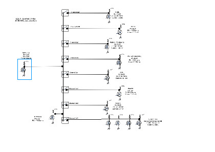
Today (Monday) I set up a Seeeduino (arduino) board connected as Master device to the mux as Master device in place of the Data Board MCU device (disconnected for now). See Diagram.
*> Note re power suuply: As part of the re-wiring every MCU device that has a USB Port is now connected via the SCS Power supply by way of a USB Cable. *
> This includes the GPS; which uses a USB-C cable. There are 4 powered devices by this way; but of course the 4th is currently powered by my MAC laptop when connected for monitoring and programming. I note that all devices show their power LED (where provided); a sure sign they have enough power to operate; but I have no idea how much power is being drawn from the supply, since INA219 is currently not operating.
*> I comment that it was somewhat of a squeeze to get those USB connectors hooked up due to space constraints; proximity to the other nearby devices.
UPDATE: I have purchased from Digikey 3 x right-angle type USB-Micro-B cables to use in place of the standard plugs plus 1x USBC right angle cable.
The small amount of space saved will make things much easier to work on the boards and tidier too.
I also purchased a couple of 2 metre USB-A to USB-micro-B cables intended to be used to connect the system plus Wifi 4G Gateway to the solar battery. One of these cables has the special waterproof plug matching the one supplied for the mains power supply.
Regarding OLED I am reasonable certain it’s signal degradation causing the problem along with lead capacitance (the old RC thing). But I cannot quite work out the exact manner in which attachment of the OLED kills the I2C bus operation. It might have excess capacitance (greater than the 10 oF assumed) or maybe it’s just causing excess current thru each I2C input MOSFET D-S or some such thing. I’d like to know what it is….
I liken this issue to impedance mismatch.
If you had the luxury to actually design the I2C bus then you would put the same value of pull-up on every device connected to the bus and have a uniform bus speed.
But unfortunately we are stuck with off the shelf components and every vendor has a different idea about what’s a good value for pull-up R.
If you have slow devices cannot handle high speed transfer then you put them on a separate bus.
Insertion of the mux unit allows more devices on the bus and segregation into segments that have matched impedance; and each segment does not offend I2C design rules such as excess current thtu the driver transistors.
I then deployed a modified version of the ‘test’ code provided by Seeed for the MUX board.
Its a simple library that sub-class encapsulates the standard wire library. The test sketch just instantiates the library then loops over each port and runs through 128 x 7 bit address on each MUX port looking for devices. I modified the sketch to iterate over every port in turn and identify the attached devices. Here is the output:
Mux Port Number: 10
Scanning Addresses:
I2C device found at 0x02
I2C device found at 0x70
Mux Port Number: 100
Scanning Addresses:
I2C device found at 0x70
Mux Port Number: 1000
Scanning Addresses:
I2C device found at 0x3C
I2C device found at 0x70
Mux Port Number: 10000
Scanning Addresses:
I2C device found at 0x3D
I2C device found at 0x70
Mux Port Number: 100000
Scanning Addresses:
I2C device found at 0x48
I2C device found at 0x49
I2C device found at 0x4A
I2C device found at 0x4B
I2C device found at 0x70
Mux Port Number: 1000000
Scanning Addresses:
I2C device found at 0x40
I2C device found at 0x70
Mux Port Number: 10000000
Scanning Addresses:
I2C device found at 0x62
I2C device found at 0x70
18 device(s) found
Note that the mux device address 0x70 appears on every channel. Really there are only 10 attached devices.
MUX Port 100 (0x3) has PM Board 2 attached; but this MCU is unaware of its I2C address right now, so it does not respond.
Apart from that, every attached device appears to be operational in this somewhat limited test; its certainly encouraging; looks like this strategy might work.
The challenge from this point is to:
(a) put the test code into a SCK SAMD device to confirm that it works the same under SAMD processor conditions. This needs to be the Data board version not the PM board version, due to the special I2C port setup (with two I2C busses).
(b) work out if there is a way to abstractly invoke the appropriate MUX port when writing and reading from one of the AUX port devices; thus not to have to modify EVERY individual i2C write and read call found in the DATA board’s firmware code. A small modification would then lend itself to code that (i) first detects the presence of the MUX device; and then (ii) conditionally uses the MUX port addressing scheme or standard wire invocations.
Why bother to do this ? This would allow the modified code could be included in the main branch of the SCS firmware instead of being isolated in a side-branch. It could be installed on devices having a MUX and on those NOT having a MUX. Thus the library that includes all of these sensors and the MUX could become part of the SCS main stream. It leads to more down-stream options for SCS.
If I COULD achieve that goal (and verify by testing) then @victor could decide if it’s safe and worthwhile to actually do that or not. Personally I think its worthwhile, because it would help to make versions of SCS having many sensors downline on the AUX bus work more reliably under condition that the various sensors purchased from myriad vendors are unable to be controlled in the way of Pull-up resistors. Everyone picks different values depending on their vision. There is no standard approach. Also BUS capacitance issues are minimised using the MUX approach.
This started as PDF file and it’s converted to jpeg format that seems the have made the text unintelligible. This forum does not allow pdf files to upload. Therefore I have shared the original file via Google drive; which includes the test code library (zipped)
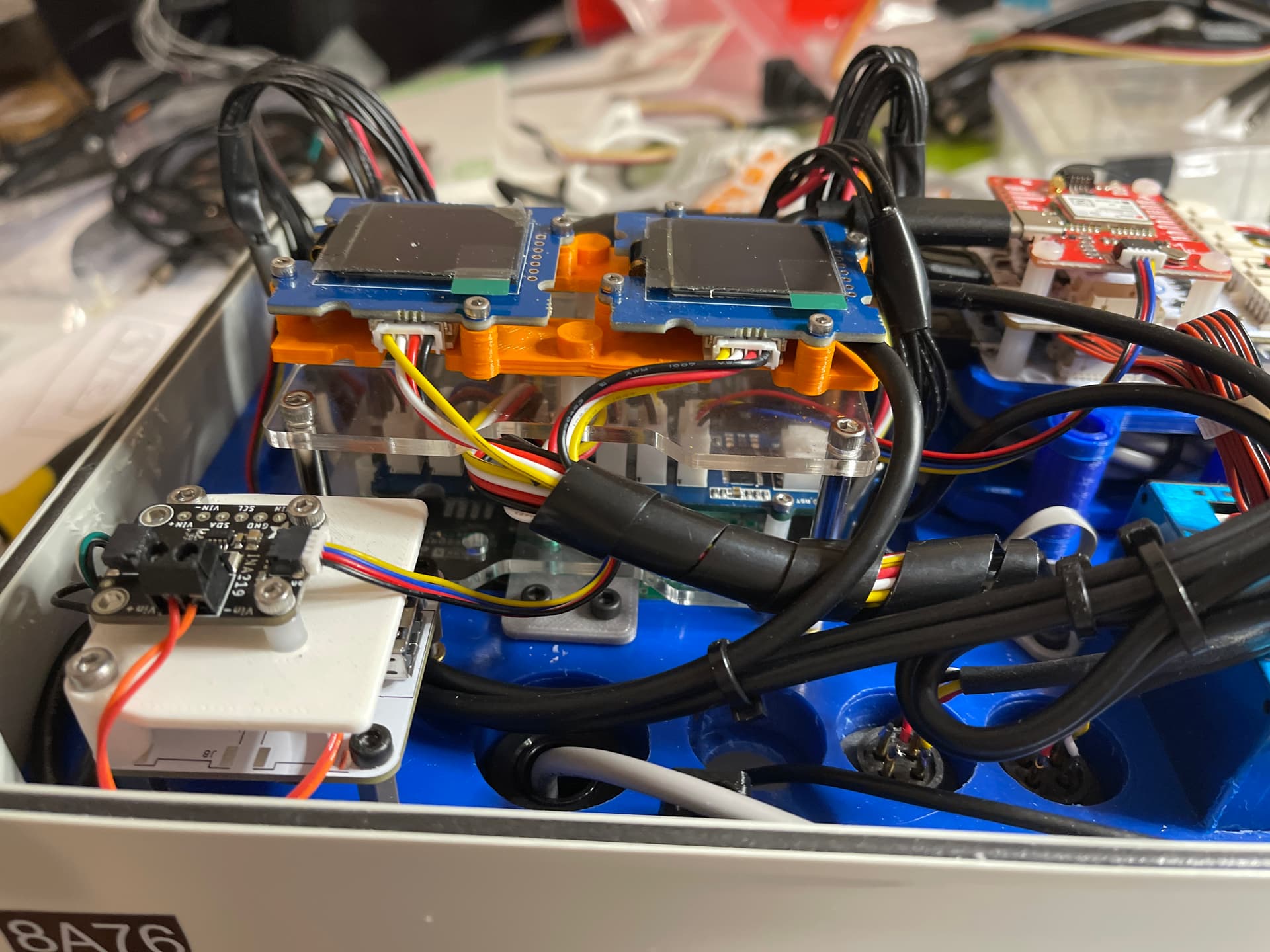
You can see the mux unit mounted below the two oled displays. I had to increase the size of the space there by using taller stand-offs.
I will also share the test code via Google drive. Look for the folder named ‘I2C mux’
Hi @oscgonfer @victor
A Further Milestone has been reached:
SCD41 device found (via the MUX) and enabled during boot sequence:::
Evidence:
11:18:52.155 → (Sck_SCD4x::start) SCD4x is asking to be started… Sensor Number:(0x6b)@ addr:(0x62)
11:18:52.155 → (Sck_SCD4x::start) localPortNum :: 0x80
11:18:52.155 → (Sck_SCD4x::start) SCD4x at Address ::x62, Channel 0x80 DETECTED
11:18:53.144 → (Sck_SCD4x::start) SCD4x device library BEGAN OK
11:18:53.539 → (Sck_SCD4x::start) Pressure Compensation set up OK
11:18:53.539 → (Sck_SCD4x::start) first Single Shot measurement requ. returned false
11:18:53.539 → (Sck_SCD4x::start) delay 5 seconds after single shot request
11:18:58.560 → (Sck_SCD4x::start) All done; returning to requestor
11:18:58.560 →
11:18:58.560 → (SckBase::EnableSensor) Started SCD4x CO2
11:18:58.560 → Enabling SCD4x CO2
11:18:58.560 → (Sck_SCD4x::start) SCD4x is asking to be started… Sensor Number:(0x6c)@ addr:(0x62)
11:18:58.560 → (Sck_SCD4x::start) localPortNum :: 0x80
11:18:58.560 → (Sck_SCD4x::start) SCD4x at Address ::x62, Channel 0x80 DETECTED
11:18:58.560 → (SckBase::EnableSensor) Started SCD4x Temperature
11:18:58.560 → Enabling SCD4x Temperature
11:18:58.560 → (Sck_SCD4x::start) SCD4x is asking to be started… Sensor Number:(0x6d)@ addr:(0x62)
11:18:58.560 → (Sck_SCD4x::start) localPortNum :: 0x80
11:18:58.560 → (Sck_SCD4x::start) SCD4x at Address ::x62, Channel 0x80 DETECTED
11:18:58.560 → (SckBase::EnableSensor) Started SCD4x Humidity
11:18:58.560 → Enabling SCD4x Humidity
Now I can move onto the next step; trying to make the system take a full set of measurements and send them to the host. I may need your help with that; as I am not certain if the host needs to be made aware of the new sensor readings (x3); or whether I need to build a new firmware for ESP (to make it aware of the new sensor too.)
Hmmm… OK; All I had to do was follow the instructions: system told me it was entering setup mode.
So (Duhhh !) I performed config using ESP in webserver mode and the result was this:
11:45:13.927 → (2021-12-30T03:45:11Z) Readings saved to flash memory.
11:45:14.423 → (2021-12-30T03:45:11Z) 10 readings saved to sdcard.
11:45:14.462 → it’s time to publish
11:45:14.462 → Recent user interaction, it’s time to publish
11:45:14.529 → (2021-12-28T05:20:09Z) Sent readings to platform.
11:45:14.529 → {t:2021-12-28T05:20:09Z,10:-1,14:52,55:18.91,56:72.47,53:31.82,58:99.87,113:3360.00,112:3235.00,89:2,87:3,88:3}
11:45:14.712 → Network publish OK!! (11 readings)
11:45:14.750 → (2021-12-28T05:21:09Z) Sent readings to platform.
11:45:14.750 → {t:2021-12-28T05:21:09Z,10:-1,14:53,55:18.89,56:72.51,53:35.02,58:99.87,113:3360.00,112:3235.00}
11:45:14.974 → Current speed: 0.00, fix: 0, hdop: 0
11:45:14.974 → it’s time to publish
11:45:14.974 → Recent user interaction, it’s time to publish
11:45:15.227 → Network publish OK!! (8 readings)
11:45:15.267 → (2021-12-30T03:45:11Z) Sent readings to platform.
11:45:15.267 → {t:2021-12-30T03:45:11Z,10:-1,14:72,55:23.68,56:63.50,53:52.10,58:99.96,89:18,87:22,88:22,96:-9999.00}
11:45:15.447 → it’s time to publish
11:45:15.447 → Recent user interaction, it’s time to publish
11:45:15.713 → Network publish OK!! (10 readings)
11:45:15.713 → ESP off…
11:45:15.976 → Current speed: 0.00, fix: 0, hdop: 0
11:45:16.966 → Current speed: 0.00, fix: 0, hdop: 0
11:45:17.970 → Current speed: 0.00, fix: 0, hdop: 0
11:45:18.968 → Current speed: 0.00, fix: 0, hdop: 0
It is unclear to me why an outlevel of 2 should get me a sequence of 1 second gps readings on screen. It might be some debug I guess.
Unfortunately thats not the end of the story: shortly after this the system just stopped.
I shall have to investigate why this happened (I guess).
OK, @oscgonfer @victor Concerning the I2C Mux integration; I believe I may have achieved some semblance of stability: it appears to be working: (Its another Milestone).
Evidence:
12:08:53.976 -> -----------
12:08:53.976 -> 2022-01-04T04:08:53Z
12:08:53.976 -> Temperature: 21.38 C
12:08:54.033 -> Humidity: 71.01 %
12:08:54.033 -> Opening TCA Channel for Device PM board Dallas Temperature at Address (0x02) on Chan (0x10)
12:08:54.509 -> PM board Dallas Temperature: 23.00 C
12:08:54.509 -> Battery: -1 %
12:08:54.618 -> Light: 206 Lux
12:08:55.014 -> Barometric pressure: 99.52 kPa
12:08:55.061 -> VOC Gas CCS811: 8.00 ppb
12:08:55.061 -> eCO2 Gas CCS811: 459.00 ppm
12:08:55.061 -> Opening TCA Channel for Device GPS Fix Quality at Address (0x42) on Chan (0x01)
12:08:55.061 -> GPS Fix Quality: 3
12:08:55.061 -> Opening TCA Channel for Device GPS Latitude at Address (0x42) on Chan (0x01)
12:08:56.615 -> GPS Latitude: 24.247045 Deg
12:08:56.724 -> GPS Longitude: 120.605133 Deg
12:08:56.724 -> GPS Altitude: 229.15 m
12:08:56.724 -> GPS Speed: 0.00 m/s
12:08:56.724 -> GPS Horizontal Dilution of Position: 144.00
12:08:56.724 -> GPS Traked Satellites: 15
12:08:56.724 -> Opening TCA Channel for Device ADS1x15 ADC 0x48 Ch0 at Address (0x48) on Chan (0x20)
12:08:56.760 -> ADS1x15 ADC 0x48 Ch0: 1.548125 V
12:08:56.760 -> ADS1x15 ADC 0x48 Ch1: 2.047937 V
12:08:56.798 -> ADS1x15 ADC 0x48 Ch2: 1.465188 V
12:08:56.798 -> ADS1x15 ADC 0x48 Ch3: 2.047937 V
12:08:56.836 -> ADS1x15 ADC 0x49 Ch0: 1.455000 V
12:08:56.836 -> ADS1x15 ADC 0x49 Ch1: 2.047937 V
12:08:56.874 -> ADS1x15 ADC 0x49 Ch2: 0.270094 V
12:08:56.874 -> ADS1x15 ADC 0x49 Ch3: 0.270031 V
12:08:56.912 -> ADS1x15 ADC 0x4A Ch0: 1.464000 V
12:08:56.912 -> ADS1x15 ADC 0x4A Ch1: 2.047937 V
12:08:56.950 -> ADS1x15 ADC 0x4A Ch2: 1.463625 V
12:08:56.988 -> ADS1x15 ADC 0x4A Ch3: 2.047937 V
12:08:56.988 -> ADS1x15 ADC 0x4B Ch0: 0.274156 V
12:08:57.026 -> ADS1x15 ADC 0x4B Ch1: 0.274500 V
12:08:57.026 -> ADS1x15 ADC 0x4B Ch2: 0.273844 V
12:08:57.059 -> ADS1x15 ADC 0x4B Ch3: 0.274094 V
12:08:57.059 -> Opening TCA Channel for Device Ext PM_A 1.0 at Address (0x02) on Chan (0x10)
12:08:57.059 -> Ext PM_A 1.0: 8 ug/m3
12:08:57.059 -> Ext PM_A 2.5: 10 ug/m3
12:08:57.059 -> Ext PM_A 10.0: 10 ug/m3
12:08:57.059 -> Ext PM_B 1.0: 9 ug/m3
12:08:57.059 -> Ext PM_B 2.5: 14 ug/m3
12:08:57.059 -> Ext PM_B 10.0: 14 ug/m3
12:08:57.059 -> -----------
This has been running now for best part of 1 hour; so I have some confidence about stability.
The stability was attained by moving the code elements relating to Mux Channel switching out of SckBase and into SckAUX (which is a better place for it). It was a lot of work; took several hours. I also changed the code to ensure Channel was only switched when the new channel is different than the current open channel.
Later, it could be moved into proposed ‘actuators’ peice.
As can be seen:
- Noise sensor on the Urban Board appears not to be functional. I will try it with another Urban board later.
- All ADC Channels are reporting results. Except 0x49 Ch 2 & 3 and 0x4B Ch 0,1,2,3 ought not be reporting anything; In fact the values reported are around 0.27 volts. Maybe this is noise ? If so maybe the inputs ought to be terminated using a resistor pulldown to 0v (and this would allow the ‘not connected’ condition to be more easily detected and ignored). ? Not sure what if anything should be done.
- INA219 (Current Sensor connected on the Power distribution Board) is not reporting results. It ought to be since it is discovered on the Aux Bus thru the MUX.
- SCD41 (SCD4x) (CO2 Gas, Humidity, Temp Sensor) is not reporting any results. It ought to be since it is discovered on the Aux Bus thru the MUX.
- I note a significant discrepancy between the (Urban Board) temp sensor and the (PM Board) Dallas Temp Sensor. I guess thats why the Dallas Temp sensor is useful to have; being more accurate.
So, my next jobs are to investigate and fix (if possible), the (3) and (4) items above.
NOTE: To get to this stage I had to install rather a lot of debug; and I found that both the GPS and OLED get called rather often (in a continuous loop; without constraint) and this made it hard to see the wood for the trees. So I was forced to install some small changes in SckBase to calm them down; basically those two devices will only update now once every second.
OK: new update:
(and another milestone.)
SCD41 CO2 sensor is now operational, along with the I2C MUX
Evidence:
20:23:20.925 -> 2022-01-06T12:23:20Z
20:23:20.925 -> Temperature: 23.01 C
20:23:20.925 -> Humidity: 70.41 %
20:23:21.427 -> PM board Dallas Temperature: 24.56 C
20:23:21.427 -> Battery: -1 %
20:23:21.427 -> Battery voltage: -1 V
20:23:21.534 -> Light: 73 Lux
20:23:21.931 -> Barometric pressure: 99.59 kPa
20:23:21.979 -> VOC Gas CCS811: 0.00 ppb
20:23:21.979 -> eCO2 Gas CCS811: 400.00 ppm
20:23:21.979 -> GPS Fix Quality: 3
20:23:21.979 -> GPS Latitude: 24.247066 Deg
20:23:21.979 -> GPS Longitude: 120.605120 Deg
20:23:21.979 -> GPS Altitude: 230.46 m
20:23:21.979 -> GPS Speed: 0.13 m/s
20:23:21.979 -> GPS Horizontal Dilution of Position: 193.00
20:23:21.979 -> GPS Traked Satellites: 12
20:23:22.010 -> ADS1x15 ADC 0x48 Ch0: 12.287812 V
20:23:23.048 -> ADS1x15 ADC 0x48 Ch1: 1.160063 V
20:23:23.048 -> ADS1x15 ADC 0x48 Ch2: 1.462500 V
20:23:23.097 -> ADS1x15 ADC 0x48 Ch3: 2.047937 V
20:23:23.097 -> ADS1x15 ADC 0x49 Ch0: 1.450688 V
20:23:23.120 -> ADS1x15 ADC 0x49 Ch1: 2.047937 V
20:23:23.120 -> ADS1x15 ADC 0x49 Ch2: 0.268562 V
20:23:23.156 -> ADS1x15 ADC 0x49 Ch3: 0.268844 V
20:23:23.189 -> ADS1x15 ADC 0x4A Ch0: 1.462562 V
20:23:23.189 -> ADS1x15 ADC 0x4A Ch1: 2.047937 V
20:23:23.223 -> ADS1x15 ADC 0x4A Ch2: 1.459250 V
20:23:23.223 -> ADS1x15 ADC 0x4A Ch3: 2.047937 V
20:23:23.256 -> ADS1x15 ADC 0x4B Ch0: 0.273062 V
20:23:23.294 -> ADS1x15 ADC 0x4B Ch1: 0.273062 V
20:23:23.294 -> ADS1x15 ADC 0x4B Ch2: 0.273250 V
20:23:23.332 -> ADS1x15 ADC 0x4B Ch3: 0.273094 V
**20:23:23.332 -> SCD4x CO2: 1775 ppm**
**20:23:23.332 -> SCD4x Temperature: 23.39 C**
**20:23:23.332 -> SCD4x Humidity: 67.52 %**
20:23:23.370 -> Ext PM_A 1.0: 18 ug/m3
20:23:23.370 -> Ext PM_A 2.5: 30 ug/m3
20:23:23.370 -> Ext PM_A 10.0: 32 ug/m3
20:23:23.370 -> Ext PM_B 1.0: 23 ug/m3
20:23:23.370 -> Ext PM_B 2.5: 39 ug/m3
20:23:23.370 -> Ext PM_B 10.0: 40 ug/m3
20:23:23.370 -> -----------
20:23:23.902 -> (2022-01-06T12:23:20Z) Readings saved to flash memory.
20:23:25.101 -> (2022-01-06T12:23:20Z) 41 readings saved to sdcard.
20:23:25.101 -> Recent user interaction, it's time to publish
20:23:25.210 -> Connecting to Wifi...
20:23:25.210 -> ESP on...
20:23:25.389 -> ESP finished booting
20:23:25.436 -> Synced config with ESP!!
20:23:25.462 -> Connecting to Wifi...
20:23:29.761 -> Connected to wifi!!
20:23:30.157 -> (2022-01-06T12:23:20Z) Sent readings to platform.
20:23:30.157 -> {t:2022-01-06T12:23:20Z,10:-1,14:73,55:23.02,56:70.42,58:99.59,113:0.00,112:400.00,71:18,72:30,73:32,75:23,76:39,77:40,96:24.56,128:3,125:24.247066,126:120.605120,127:230.46,129:0.13,131:193.00,130:12,133:12.287812,134:1.160063,135:1.46250
20:23:31.248 -> Network publish OK!! (41 readings)
20:23:31.248 -> ESP off...
Notes: the actual CO2 reading seems somewhat high. I will ignore this issue for now and move onto the next challenge, I am hoping it will settle down to 400-500 ppm sooner or later; and hopefully the automatic self calibration will make that happen without intervention. [I would be feeling pretty poorly by now if the actual CO2 concentration in my workshop was so high]; Both the Temp and Humidity readings differ from those on the Urban Board. This is expected due to heating by the CO2 sensor.
The temp is adjusted using an offset mechanism based on the Dallas temp probe. The device is also pressure compensated using readings taken from the Barometric pressure sensor.
Remaining challenges:
INA219 sensor is physically connected to the main 5 volt power for the SCS. I want to measure power consumption because ultimately the system will be solar powered; but the solar battery provides no instrumentation at all; so at least the INA219 can provide Voltage and current drain.
The sensor is already integrated; but it (was) disabled in firmware.
It is being detected during I2C bus scann at bootup time; therefore it ought to be working; but it produces no output. So I will investigate and see why this is the case; hopefully it should be simple.
Further down the agenda we have:
(a) integration of a 2nd OLED display. It will display some output of some selected sensors.
(b) finalise integration of the wind and rain sensors along with 2nd PM board. The code for PM Board 2 is written; needs tweaking and firmware uploading. then integration coding needs to be written from scratch for the main data board to bring it on line with the two new sensors (8 different readings).
(c) put the new firmware into the real production Data Board; and hope to see the readings appear on the map display.
(d) @oscgonfer has committed to host system coding needed to convert Gas sensor voltage readings into gas concentrations and identify the gases. This is needed because I am using sensors supplied by Spec Sensors (US) company; instead of Alphasense sensors. Both brands are electrochemical in design and work in a similar way; thus the integration should be straightforward.
I have not heard about this from him for awhile; so I do not know where its at.
Just a late night comment:
Yes indeed it proved simple in the end to find out why the INA219 was not working.
It turned out the I2C address in the firmware code was set to the wrong I2C address: 0x41 when it should have been the default 0x40.
However having fixed that small issue; now I find that other devices connected to the mux no longer work whilst the channel for the INA219 is open. (I am allowing up to 3 channels on the mux to be open at once.)
This thing is fighting me all the way; but I am very persistent !!
I guess thats easy to fix (tomorrow).
I got the INA219 working and then moved on to getting the second PM MCU working; that connects direct to the Anemometer and Rain gauge by Uart serial.
But the handling of I2C mux has become unstable (again).
The issue with that is the 2nd pm board is not recognised when the Data board MCU performs I2C discovery.
I am using an special technique in debugging this; I found a piece of software for my MacBook that can monitor two usb serial ports simultaneously; thus I can see requests being sent to the pm board; and then how the requests being handled by the pm board. So far I observe it’s not seeing them reliably.
Code for this piece is same as PM Board #1 but with a different slave address 0x12
To quote a great man “ we do not do these things because they are easy; we do them because they are hard…” and this above issue is like that !
I’ve been tidying up the code a bit, came across the ‘Inspect’ functionality in PlatformIO.
So I ran it.
At the end of a great deal of output I saw this:
/Users/brynparrott/Documents/Platformio/projects/smartcitizen-kit-21-WIP/sam/.platformio/packages/toolchain-gccarmnoneeabi/bin/…/lib/gcc/arm-none-eabi/7.2.1/…/…/…/…/arm-none-eabi/bin/ld: .pio/build/sck2/firmware.elf section
.text' will not fit in regionFLASH’\n/Users/brynparrott/Documents/Platformio/projects/smartcitizen-kit-21-WIP/sam/.platformio/packages/toolchain-gccarmnoneeabi/bin/…/lib/gcc/arm-none-eabi/7.2.1/…/…/…/…/arm-none-eabi/bin/ld: region `FLASH’ overflowed by 51932 bytes\ncollect2: error: ld returned 1 exit status\n*** [.pio/build/sck2/firmware.elf] Error 1\n========================= [FAILED] Took 13.63 seconds ========================="
Looks like a showstopper to me.
It might explain what I have been seeing: that the firmware becomes unstable when I add in more ‘debugging’ print statements. I have been finding that it appears to just stop.
Of course each print statement has some text with it. Presumably the compiler/linker just stashes it into ‘.text’.
If ‘.text’ overflows. I guess that the firmware ‘treads on’ some other area of memory; and possibly causes misoperation.
Of course my understanding of what ‘.text’ is all about might not be correct.
Some of the ‘bugs’ I have been trying to fix might simply have been due to this, and not my actual code…
So, its looking like I need to go through and remove most of my debugging print (sprintf) statements;
I have to find ~60K’s worth; which seems like a lot.
And the question remains as to how I am going to localise issues that crop up. I have already established that the debugger is pretty useless; because IT wants to add a bunch of symbols into the code that also expand the memory footprint. It’s too much; and the firmware refuses o load at all.
> {This is the reason I was hoping to be able to use Atmel Studio; and get a better idea of whats going on }
What is surprising is that PlatforIO has been happy to build the firmware and deliver ‘SUCCESS’ at the end; and using a verbose build; it tells me that :
Advanced Memory Usage is available via "PlatformIO Home > Project Inspect"
RAM:   [========  ]  76.4% (used 25028 bytes from 32768 bytes)
Flash: [========= ]  92.4% (used 242324 bytes from 262144 bytes)
.pio/build/sck2/firmware.elf  :
section             size        addr
.text             241580        8192
.ARM.exidx             8      249772
.data                736   536870912
.bss               24292   536871648
.ARM.attributes       40           0
.comment             126           0
.debug_frame        7300           0
.stabstr             441           0
Total             274523
Which seems misleading; given that ‘Inspect’ tells me I am using too much.
Any guidance ( @oscgonfer @victor ) you might want to offer would be welcome at this time; but its looking like I have a lot of work to do here.
I want to use a different processor: one with more FLASH. I need to live within the available resources…
…